4-Layer PCB for EV Charging Stations: Complete Design, Material & Manufacturing Guide
With the rapid adoption of electric vehicles, EV charging stations (EV Charging Stations) demand ever-higher reliability, communication capability, electrical safety, and long-term stability from their control systems. In modern AC and DC chargers, the control board typically integrates a microcontroller, communication interfaces, voltage and current sensing, relay or contactor drivers, temperature detection, fault protection, and human-machine interaction.
Compared to traditional 2-layer PCBs, a 4-layer PCB provides more routing space, a solid ground plane, better power integrity, and greater flexibility for EMC design. As a result, the 4-layer control board has become a practical choice for many medium-to-high complexity charging station control systems.
This article systematically covers 4-layer PCB structure, charging station control board functions, PCB materials, routing design, thermal management, EMC, manufacturing processes, reliability, and cost – offering a valuable reference for EV charging equipment OEMs, electronic engineers, and PCB procurement professionals.
What Is a 4-Layer PCB for Charging Stations?
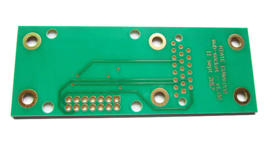
A 4-layer PCB is a multilayer circuit board formed by laminating four copper foil layers with insulating dielectric materials such as core and prepreg. A typical 4-layer charging pile control board may use this stack-up:
- L1: Top signal layer + component layer
- L2: Full GND ground plane
- L3: Power layer + auxiliary signal layer
- L4: Bottom signal layer + some components
This structure provides greater routing capacity within a limited board area while improving high-speed signal return paths and power distribution. For charging station control systems, 4-layer PCBs are especially well-suited for complex boards that include MCU, CAN, RS-485, Ethernet, Wi-Fi or cellular, RFID, voltage/current/temperature sensing, relay/contactor drivers, protection circuits, and display interfaces.
At gopcb, the actual stack-up for EV charging station PCBs is customized based on operating voltage, control architecture, PCB dimensions, copper weight, communication speed, thermal environment, and EMC requirements.
Why Use a 4-Layer PCB for Charging Station Control Boards?
Not all charging stations require a 4-layer PCB. For simple control systems with few components, a 2-layer board may suffice. However, when integrating multiple communication, sensing, and control functions, 4-layer PCBs offer clear advantages.
1. More Routing Space
Modern smart charging stations incorporate numerous electronic functions: MCU, power management, current/voltage sampling, temperature sensing, CAN, RS-485, Ethernet, Wi-Fi, 4G/5G, RFID, display interfaces, relay/contactor drivers, surge and ESD protection. Routing all these on a 2-layer board can be extremely cramped. A 4-layer board adds internal copper layers, distributing power, ground, and some signals across different layers to reduce routing congestion.
2. Improved Grounding Design
One of the biggest advantages of a 4-layer PCB is the ability to provide a continuous internal ground plane. A solid GND layer offers a stable, low-impedance return path for high-speed signals and reduces loop area. For charging station control boards, where high-power switching devices, power modules, and relay operations can generate EMI, a well-designed ground plane is essential.
3. Better EMC Performance
Charging stations simultaneously handle high voltage, high current, and digital communication circuits, making EMC design critical. A well-designed 4-layer PCB helps reduce signal loop area, radiated emissions, crosstalk, ground bounce, high-frequency return path impedance, and power noise. However, adding layers alone does not automatically solve EMC issues – effective design requires combining stack-up, component placement, ground planes, signal return paths, power distribution, high-low voltage isolation, and external interface protection.
4. Enhanced Power Integrity
Using the third layer for power distribution (or a power plane) allows more efficient allocation of different voltage rails. Compared to long power traces on a 2-layer board, a 4-layer structure reduces impedance and voltage drop, which is especially important for noise-sensitive devices like MCUs, communication chips, and sensors.
5. Higher Component Integration
As smart charging piles gain more features, the number of components and circuit complexity increases. A 4-layer PCB supports higher routing density within the same board area, making it ideal for smart AC chargers, DC fast chargers, wall-mounted chargers, commercial charging equipment, industrial-grade systems, and EV charging controllers.
Typical 4-Layer PCB Stack-Up for Charging Stations
A typical EV charging station PCB stack-up might be:
- L1 (Top): MCU and main ICs, critical components, high-speed signals, some power traces, key control signals.
- L2 (Ground): Continuous GND reference plane for low-impedance return paths, signal integrity, EMI reduction, crosstalk suppression, and improved power integrity.
- L3 (Power + Signal): Low-voltage power distribution, auxiliary signals, some control lines, local power planes.
- L4 (Bottom): Auxiliary signals, low-speed control lines, some components, connector-related traces.
The actual stack-up must be determined with the PCB manufacturer based on material thickness, dielectric layer thickness, and copper weight – not by copying a generic template. For high-speed communication interfaces, impedance must be calculated using actual dielectric thickness and Dk, and verified by the manufacturer.
What Circuits Are Typically Included on a Charging Station Control Board?
A complete EV charger control board typically handles multiple control and monitoring functions:
- MCU microcontroller: Manages charging status, charge flow, fault detection, user authentication, communication, contactor control, temperature/voltage/current monitoring.
- Communication interfaces: CAN, RS-485, Ethernet, Wi-Fi, Bluetooth, 4G/5G cellular. High-speed lines require proper impedance, reference planes, signal return, and differential pair layout.
- Voltage and current sensing: Requires high accuracy, low noise, isolation, sampling bandwidth, and careful analog/digital ground partitioning. For high-voltage systems, reliable electrical isolation is mandatory.
- Protection circuits: Overvoltage, overcurrent, overtemperature, short-circuit, surge, ESD, and EFT protection. Placement of protective devices close to external connectors is critical.
- Relay and contactor control: Driver circuits with appropriate isolation and protection for the voltage levels involved.
What Material Should Be Used for a 4-Layer Charging Station PCB?
Material choice directly affects thermal performance, electrical properties, mechanical reliability, and service life.
- FR-4: The most common substrate. For many control-type charging station PCBs, standard FR-4 meets basic needs with low cost, stable supply, good mechanical strength, mature manufacturing processes, and wide availability. Suitable for moderate operating temperatures without special high-speed requirements.
- High-Tg FR-4: For higher operating temperatures or long-term reliability, high-Tg FR-4 offers better thermal stability. Ideal for high-temperature environments, frequent thermal cycling, high component density, lead-free soldering, and continuous operation. This is a common choice for high-reliability charging station 4-layer boards.
- Halogen-free materials: For projects with stricter environmental and material compliance requirements.
The final material should be selected based on operating temperature, electrical performance, reliability, environmental requirements, cost, and production volume.
Key Design Considerations for 4-Layer Charging Station PCBs
Impedance Control
If the board includes high-speed communication interfaces, impedance control is necessary. Differential pairs must be designed with target impedance based on line width, spacing, copper thickness, dielectric thickness, and Dk. Always confirm the stack-up with the manufacturer early in design, not after layout is complete.
Trace Width
Trace width must be determined by current and temperature rise. Factors include operating current, copper weight, allowable temperature rise, board space, trace length, and ambient temperature. Low-current signal lines and power traces should follow different design rules.
Creepage and Clearance
Because charging stations involve mains and high DC voltages, creepage and clearance distances are critical safety parameters. Requirements depend on working voltage, overvoltage category, pollution degree, insulation type, and applicable product standards. Adequate isolation must be maintained between high-voltage and low-voltage control areas.
GND Plane Design
A 4-layer PCB typically uses one layer as a solid ground plane. However, in isolated systems, not all areas can simply be filled with GND. Regional design must consider isolation structure, safety distances, power architecture, and signal return paths.
Via Design
Vias interconnect the four layers. Consider hole diameter, finished hole size, aspect ratio, via spacing, current-carrying capacity, clearance to copper, and manufacturing tolerances. For most standard control boards, conventional through-hole vias are adequate.
Thermal Management and Power Integrity for Charging Station PCBs
Although the control board may not carry the full charging current, multiple heat-generating components exist: DC/DC converters, MOSFETs, power management ICs, relay drivers, communication modules, and protection devices. Thermal management is essential. Common methods include increasing copper area, using thermal vias, spreading copper, placing heat sources strategically, using heat sinks, thermal interface materials, and optimizing enclosure airflow. For sensitive devices like MCUs and communication chips, decoupling capacitors should be placed as close as possible to IC power pins, and high-frequency switching current loops should be kept short.
EMC and Signal Integrity Design for EV Charging Station PCBs
Integrating high-power circuits with digital control, analog sensing, and communication makes EMC design paramount.
- Separate noisy and sensitive circuits: Keep high-noise areas (high-frequency switching supplies, relay drives, high-current switches, contactor drivers) apart from sensitive areas (analog sampling, MCU, communication interfaces, low-level sensors, clock lines).
- Minimize high-frequency current loops: Smaller loop areas reduce EMI risk.
- Maintain continuous signal return paths: High-speed traces need a stable reference plane. Avoid splits or gaps under the signal path.
- Reinforce external interface protection: Place TVS, filters, or other protection devices near connectors that are exposed to ESD, surge, EFT, and external interference.
Manufacturing Process for 4-Layer Charging Station PCBs
A professional manufacturing process typically includes:
- Engineering data review: Gerber, drill files, stack-up, BOM, dimensions, copper weight, impedance requirements, surface finish, special tolerances. Early DFM review identifies potential risks.
- Material preparation: Core, prepreg, copper foil – thickness and dielectric properties must meet design.
- Inner layer fabrication: Imaging, exposure, development, etching, AOI inspection.
- Lamination: Press inner layers, prepreg, and copper foil under controlled temperature, pressure, and time.
- Mechanical drilling: Drill holes according to the drill file – precision affects interlayer reliability.
- Electroless copper and electroplating: Deposit conductive copper on hole walls for interlayer connections.
- Outer layer fabrication: Pattern transfer, exposure, development, etching.
- Solder mask and silkscreen: Protect copper and provide component labels, polarity, connector names, warnings, and product info.
- Surface finish: Options include HASL, lead-free HASL, ENIG, OSP. For fine-pitch components and high surface reliability, ENIG is a common choice.
- Electrical testing and quality inspection: AOI, flying probe, electrical test, dimensional check, cross-section analysis, solderability test, impedance test – tailored to product requirements.
Reliability Requirements for Charging Station PCBs
Charging stations may operate outdoors, in industrial environments, or at high temperatures, so the control board must have excellent long-term reliability.
- Thermal cycling reliability: Repeated heating and cooling stress PCB copper, vias, solder joints, components, and substrate. Material selection and consistent manufacturing are vital.
- Moisture resistance: Outdoor stations face high humidity, temperature changes, condensation, and rain. PCB design must consider enclosure protection and environment. Conformal coating may be used for high-reliability applications.
- Electrical isolation: Maintain reliable isolation between high-voltage and low-voltage areas, especially for AC input, DC output, contactors, relays, high-voltage sensing, isolated communication, and isolated power.
- Corrosion resistance: In humid, salty, or industrial environments, appropriate surface protection is necessary.
- Manufacturing consistency: For volume production, consistent copper thickness, board thickness, hole size, layer registration, surface finish, impedance, and dimensions are critical.
How Much Does a 4-Layer Charging Station PCB Cost?
The price is not determined by layer count alone. Factors include PCB size, order quantity, board thickness, copper weight, substrate type, minimum trace/space, number of holes, surface finish, impedance control, special vias, testing requirements, lead time, and conformal coating. For small batch prototypes with standard FR-4 and conventional requirements, prices may range from $5–$30 per board. High-Tg material, heavy copper, special surface finish, impedance control, or complex processes increase cost. In volume production, unit costs drop significantly as engineering and setup costs are amortized. For an accurate quote, submit Gerber files, board thickness, copper weight, quantity, and process requirements to gopcb.
4-Layer vs. 2-Layer PCB: Which Is Better for Charging Stations?
For simple controllers, a 2-layer PCB may suffice. For smart charging stations with multiple communication, sensing, and control functions, a 4-layer board offers clear advantages.
- 2-layer: Lower cost, simpler manufacturing, suitable for simple systems, but limited routing, poor ground integrity, harder EMC optimization, difficult high-speed routing, and restricted component density.
- 4-layer: More routing space, solid ground plane, better signal integrity, improved power distribution, higher integration, and greater EMC flexibility.
For intelligent EV charging station control boards with MCU, CAN, RS-485, Ethernet, sensors, relay control, and multiple protection circuits, a 4-layer PCB is often the most balanced choice between performance and cost.
How to Choose a 4-Layer Charging Station PCB Manufacturer
Selecting the right PCB manufacturer is critical for reliability and volume stability. Evaluate suppliers on:
- 4-layer and multilayer PCB fabrication
- High-Tg FR-4 processing
- Impedance control
- High-voltage PCB experience
- Heavy copper PCB capability
- Fine-line processing
- Industrial and automotive electronics experience
- Prototype and volume production capabilities
A good manufacturer not only produces PCBs but also provides DFM and manufacturing advice during the engineering phase. gopcb offers custom PCB manufacturing services for EV charging equipment, including engineering review, prototyping, and volume production with various materials, copper weights, surface finishes, and multilayer stack-ups.
For a quote, provide Gerber files, PCB dimensions, layer count, board thickness, copper weight, material, surface finish, order quantity, annual demand, impedance requirements, and special reliability needs. This enables accurate cost and lead-time evaluation.
Explore our capabilities: PCB manufacturing, prototype PCB assembly, turnkey PCB assembly, high-volume PCB assembly, and SMT PCB assembly.
FAQ: 4-Layer Charging Station PCBs
Q1: Is a 4-layer PCB suitable for EV charging stations?
Yes. It provides more routing space, a solid ground plane, better power distribution, and greater EMC design flexibility – ideal for medium-to-high complexity charger control systems.
Q2: What material is commonly used for 4-layer charging station PCBs?
FR-4 is the most common. For high-temperature or long-term reliability, high-Tg FR-4 is recommended.
Q3: What is the price range for a 4-layer charging station PCB?
Small-batch prototypes with standard FR-4 typically range from $5–$30 per board, but actual cost depends on size, quantity, copper weight, thickness, surface finish, material, and special requirements.
Q4: Is a 4-layer PCB always better than a 2-layer PCB?
Not always. For very simple circuits, 2-layer may be more economical. However, for systems with multiple communication interfaces, sensors, power management, and protection circuits, 4-layer boards enable high-density routing, solid grounding, and easier EMC optimization.
Q5: Is high-Tg material mandatory for charging station PCBs?
No. The decision depends on operating temperature, thermal cycling, product lifetime, reliability requirements, and cost.
Q6: Is ENIG a good surface finish for charging station control boards?
ENIG is suitable, especially for fine-pitch components and high solder reliability. The final choice should balance cost, SMT process, component types, and product life.
Q7: Can a 4-layer PCB carry high current?
Yes, but design must account for current, copper weight, trace width, temperature rise, and cooling. Heavy copper or increased copper area may be needed for high-current paths.
Conclusion
A 4-layer PCB for EV charging stations is a practical solution for modern smart charger control systems. Compared to 2-layer boards, it offers greater routing space, a solid GND reference plane, better signal integrity, more efficient power distribution, higher component integration, and greater EMC design flexibility. However, a truly reliable 4-layer control board requires systematic design across material selection, stack-up, trace/space, impedance, creepage/clearance, thermal management, grounding, EMC, high-low voltage isolation, and manufacturing processes.
For charging station OEMs and EV equipment manufacturers, engaging with a professional PCB manufacturer early in the design phase can resolve stack-up, material, impedance, tolerances, and DFM issues – reducing the risk of board re-spins. gopcb provides custom multilayer PCB manufacturing for EV charging and industrial control applications, including 4-layer prototyping, volume production, high-Tg PCBs, heavy copper, impedance-controlled PCBs, and various surface finishes – supporting you from design validation to mass production.