RF PCB Design Guide: Key Principles, Layout Techniques, Materials, and Best Practices
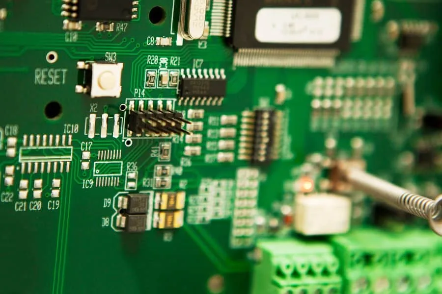
When electronic systems operate at high frequencies, RF PCB design requires much greater attention to signal integrity, impedance control, grounding, materials, and component placement than conventional PCB design. As operating frequencies increase, even small changes in trace geometry, dielectric thickness, via structure, or return-current paths can affect electrical performance.
A well-designed RF PCB provides stable signal transmission, controlled impedance, low insertion loss, reduced electromagnetic interference (EMI), and reliable overall performance. For microwave and high-frequency applications, engineers must carefully plan the PCB stackup, transmission lines, grounding structure, component placement, and manufacturing tolerances before fabrication.
For demanding RF applications, Kingda focuses on manufacturing considerations that support high-frequency PCB performance, helping customers translate RF designs into manufacturable and reliable circuit boards.
Key Takeaways
- Use short, direct RF traces with controlled geometry to minimize insertion loss and unwanted parasitic effects.
- Design transmission lines according to the required characteristic impedance, with 50-ohm impedance control being common in many RF systems.
- Maintain a continuous reference ground plane beneath RF transmission lines to provide a low-inductance return-current path.
- Separate RF circuits from noisy digital and power sections to reduce electromagnetic coupling and crosstalk.
- Select appropriate low-loss PCB materials according to operating frequency, dielectric properties, thermal requirements, and application environment.
- Carefully optimize the PCB stackup to maintain consistent impedance and predictable electromagnetic behavior.
- Minimize unnecessary vias in RF signal paths and use appropriately placed ground vias to improve return-current continuity.
- Use electromagnetic and signal-integrity simulation before fabrication whenever the design operates at demanding frequencies.
- Validate the finished RF PCB using appropriate high-frequency test equipment and production inspection methods.
- Consider manufacturability from the beginning to control tolerances, improve yield, and reduce redesign costs.
What Is RF PCB Design?
An RF PCB is a printed circuit board designed to transmit, process, or distribute radio-frequency signals. RF circuit boards are widely used in wireless communication equipment, radar systems, satellite communication, IoT devices, automotive electronics, test equipment, medical electronics, and other high-frequency applications.
Unlike low-speed digital circuits, RF circuits are highly sensitive to physical geometry and electromagnetic behavior. Parameters such as trace width, copper thickness, dielectric constant, dielectric thickness, surface roughness, and distance to the reference plane can directly influence electrical performance.
Therefore, RF PCB design should not be treated simply as conventional PCB layout at a higher clock speed. It requires an integrated approach involving circuit design, electromagnetic analysis, material selection, stackup engineering, PCB fabrication, assembly, and testing.
Core Principles of High-Frequency PCB Design
1. Signal Integrity
Signal integrity is one of the most important considerations in high-frequency PCB design. It describes how accurately an electrical signal maintains its intended amplitude, timing, waveform, and energy while traveling through the PCB.
At high frequencies, signals can experience attenuation, reflection, dispersion, crosstalk, and electromagnetic radiation. Poor routing practices may therefore result in insertion loss, waveform distortion, unstable transmission, or reduced system sensitivity.
To improve signal integrity:
- Keep RF traces as short as practical.
- Avoid unnecessary routing changes and discontinuities.
- Use controlled-impedance transmission lines.
- Avoid abrupt changes in trace width.
- Minimize unnecessary vias and connectors.
- Maintain a continuous reference plane.
- Keep sensitive RF paths away from noisy digital signals.
- Avoid routing high-speed signals across gaps or splits in the reference plane.
Trace geometry should be selected based on the PCB stackup and required impedance rather than simply choosing the widest possible trace.
Design Tip: In RF applications, electrical length is often more important than physical length alone. A trace that appears short on a conventional PCB can still behave as a significant transmission-line structure at sufficiently high frequencies.
2. Impedance Matching
Impedance matching is fundamental to RF and microwave PCB performance.
When the impedance of the source, transmission line, and load is not properly controlled, part of the signal energy can be reflected toward the source. These reflections may increase insertion loss, create standing waves, and degrade overall system performance.
Many RF systems use a nominal 50-ohm transmission-line impedance, although other impedance values may be required depending on the application.
The characteristic impedance of a PCB transmission line is influenced by several factors, including:
- Trace width
- Copper thickness
- Dielectric constant
- Dielectric thickness
- Distance to the reference plane
- Trace geometry
- PCB material properties
- Surface roughness
For this reason, impedance should be considered during stackup development rather than being treated as a final layout check.
Engineers can use field-solver software, impedance calculators, and electromagnetic simulation tools to determine appropriate trace dimensions.
Important: Even small variations in dielectric thickness or trace width can affect impedance at high frequencies. Manufacturing tolerances should therefore be considered during the design stage.
3. Ground Plane and Return-Current Path
A continuous ground plane is one of the most important structures in an RF PCB.
High-frequency current does not simply return through the lowest-resistance path. The return current tends to follow a path associated with the electromagnetic field distribution and therefore remains closely coupled to the signal trace when a suitable reference plane is available.
A continuous reference plane helps:
- Provide a low-inductance return-current path
- Reduce loop area
- Improve electromagnetic compatibility
- Reduce unwanted radiation
- Improve impedance consistency
- Reduce crosstalk
- Improve overall signal integrity
For RF transmission lines, avoid routing across slots, voids, or unnecessary splits in the reference plane.
Recommended practices include:
- Place the reference plane directly beneath the RF transmission line whenever the stackup permits.
- Keep the RF return path continuous.
- Connect ground regions with strategically placed ground vias.
- Avoid unnecessary gaps or isolated copper islands.
- Use via stitching where appropriate to improve grounding and electromagnetic containment.
- Keep high-current digital return paths from interfering with sensitive RF return paths.
Ground Plane Best Practices
| Design Practice | Why It Matters |
|---|---|
| Continuous ground plane | Provides a predictable return-current path |
| Short RF traces | Reduces loss and parasitic effects |
| Controlled trace geometry | Maintains consistent impedance |
| Proper via stitching | Improves grounding and RF isolation |
| Avoid ground-plane splits | Prevents return-path discontinuities |
| Appropriate stackup | Supports impedance and signal integrity |
Remember: In high-frequency PCB design, the ground plane is not simply a connection point for ground pins. It is an essential part of the transmission-line structure and electromagnetic return path.
4. RF Component Placement
Component placement has a direct impact on RF performance.
RF components should generally be positioned according to the signal-flow path. Components that form a single RF chain should be placed close enough to minimize interconnect length while maintaining appropriate isolation from unrelated circuits.
For example, a typical RF signal chain may include:
RF Connector → Filter → Amplifier → Mixer → Filter → RF Output
The physical placement should follow this functional sequence whenever possible.
Recommended practices include:
- Keep RF components close to each other.
- Minimize the distance between matching networks and their associated components.
- Place RF connectors near the PCB edge where practical.
- Keep antennas and RF connectors away from noisy digital circuits.
- Separate RF, analog, digital, and high-power sections according to the system architecture.
- Provide sufficient space for tuning components and test points.
- Avoid placing sensitive RF components near high-speed digital interfaces, switching regulators, or high-current power paths.
Good placement reduces unnecessary routing and makes impedance control easier.
RF PCB Design Workflow
A reliable RF PCB design process should begin before PCB routing. Each stage should be carefully coordinated to prevent expensive design changes later.
1. Circuit and System Planning
Start with a complete schematic that clearly defines the RF signal path, power architecture, control signals, and interfaces.
Identify:
- RF input and output paths
- Filters
- Amplifiers
- Matching networks
- Oscillators
- Mixers
- Antenna interfaces
- Power supply sections
- Digital control circuits
- Test points
RF and digital sections should be clearly identified from the beginning.
At this stage, engineers should also define key electrical requirements such as:
- Operating frequency
- Required characteristic impedance
- Maximum insertion loss
- Return loss targets
- Power level
- Noise sensitivity
- Isolation requirements
- Environmental conditions
Early simulation can help identify potential signal-integrity or matching problems before PCB layout begins.
2. Component Placement
After schematic planning, place components according to the RF signal flow.
High-frequency components should generally be kept close together, but physical proximity alone is not sufficient. Isolation and electromagnetic coupling must also be considered.
A practical placement strategy includes:
- Divide the board into RF, analog, digital, and power regions.
- Keep RF signal chains compact.
- Place decoupling capacitors close to the corresponding power pins.
- Keep matching networks close to RF components.
- Minimize unnecessary interconnects.
- Provide adequate space for measurement and tuning.
- Keep sensitive RF circuits away from switching power supplies.
RF Component Placement Checklist
- Separate RF and digital functional areas.
- Keep critical RF components close together.
- Minimize RF interconnect length.
- Place matching components close to their associated RF pins.
- Keep connectors and antennas appropriately positioned.
- Provide accessible test points where required.
- Consider shielding requirements during placement.
3. RF Trace Routing
RF routing is one of the most critical stages of PCB layout.
Unlike ordinary low-speed routing, RF traces should be treated as controlled transmission lines. Their width, spacing, reference-plane relationship, and geometry must remain consistent.
Recommended RF Routing Practices
- Keep critical RF traces short and direct.
- Maintain consistent trace width.
- Avoid abrupt changes in geometry.
- Use smooth bends or appropriately designed 45-degree transitions.
- Avoid unnecessary routing through multiple layers.
- Minimize vias in RF signal paths.
- Keep adequate spacing between sensitive RF traces.
- Maintain a continuous reference plane beneath the transmission line.
- Keep RF traces away from noisy digital signals.
- Avoid routing across ground-plane gaps or splits.
For controlled-impedance applications, microstrip and stripline structures are commonly used.
Microstrip
A microstrip consists of a surface trace referenced to a ground plane on an adjacent PCB layer. It is relatively easy to fabricate and inspect, making it widely used in RF and high-frequency PCB applications.
Stripline
A stripline is embedded between reference planes. It provides strong electromagnetic containment and can offer excellent isolation, although fabrication and layer-stack requirements can be more demanding.
The appropriate transmission-line structure depends on frequency, board architecture, impedance requirements, loss targets, manufacturing capability, and cost.
4. PCB Stackup Design
The PCB stackup is critical to RF performance because it determines the physical relationship between signal layers, dielectric materials, and reference planes.
For RF applications, the transmission line should have a predictable relationship with its reference plane.
A simplified four-layer structure might be:
| Layer | Typical Function |
|---|---|
| Layer 1 | RF and critical signals |
| Layer 2 | Solid ground plane |
| Layer 3 | Power and selected signals |
| Layer 4 | Digital and auxiliary signals |
This is only an example. Actual stackup selection should be based on the required impedance, frequency range, material properties, mechanical constraints, thermal requirements, and manufacturing capabilities.
For more demanding RF systems, multilayer constructions with dedicated RF layers and multiple reference planes may be more appropriate.
Stackup Design Considerations
- Dielectric thickness
- Dielectric constant
- Dissipation factor
- Copper thickness
- Surface roughness
- Controlled impedance
- Thermal expansion
- Manufacturing tolerance
- RF isolation
- Mechanical thickness
Design Tip: Develop the PCB stackup together with the PCB manufacturer whenever possible. This allows the calculated impedance model to reflect realistic fabrication tolerances.
5. Via Management
Vias are essential for multilayer PCB interconnection, but they can introduce parasitic inductance and capacitance into RF structures.
Unnecessary vias in critical RF paths should therefore be avoided.
When a signal must transition between layers:
- Minimize the via transition length.
- Keep the surrounding geometry controlled.
- Use appropriate via structures.
- Provide a nearby ground-via path where necessary.
- Avoid unnecessary stubs.
- Consider back-drilling for high-speed structures where appropriate.
- Simulate critical transitions when operating frequency and electrical length justify it.
Ground vias can also be used strategically to create via fences around sensitive RF regions and improve isolation.
Important: Via design should be evaluated as part of the complete transmission-line structure rather than as an isolated PCB feature.
RF PCB Material Selection
Material selection becomes increasingly important as frequency increases.
Standard FR-4 can be suitable for many applications, but demanding RF and microwave designs may require specialized low-loss materials with tighter dielectric-property control.
Important material parameters include:
Dielectric Constant (Dk)
The dielectric constant affects propagation velocity and transmission-line impedance. At high frequencies, variations in Dk can affect phase behavior and impedance consistency.
Dissipation Factor (Df)
The dissipation factor indicates dielectric loss. Lower Df materials are generally preferred for applications where minimizing transmission loss is important.
Copper Surface Roughness
At high frequencies, conductor loss is influenced by current distribution near the conductor surface. Copper surface roughness can therefore contribute to increased RF loss.
Thermal Stability
Material properties can change with temperature. For RF applications operating across a wide temperature range, stable dielectric and mechanical characteristics are important.
Key Material Factors
| Material Factor | RF Impact |
|---|---|
| Dielectric constant (Dk) | Affects impedance and propagation characteristics |
| Dissipation factor (Df) | Influences dielectric loss |
| Copper roughness | Influences conductor loss |
| Dielectric thickness | Affects transmission-line impedance |
| Thermal stability | Supports consistent performance across temperature |
| Dimensional stability | Helps maintain predictable PCB geometry |
The material should therefore be selected based on the actual frequency range, loss requirements, power level, environmental conditions, and manufacturing process.
Common RF PCB Design Pitfalls
1. Poor Grounding
Breaking the reference plane or creating an unintended return-current discontinuity can significantly degrade RF performance.
Avoid unnecessary slots, isolated copper regions, and plane interruptions beneath critical RF traces.
2. Excessively Long RF Traces
Long interconnects increase loss and may introduce additional parasitic effects. Keep critical RF paths as short as practical.
3. Inconsistent Trace Width
Changing trace width without accounting for impedance can create discontinuities and reflections.
4. Poor RF/Digital Isolation
Fast digital interfaces and switching power circuits can generate broadband electromagnetic noise. Placing them too close to sensitive RF circuits may result in coupling and interference.
5. Improper Material Selection
A material suitable for low-frequency digital applications may not provide the required loss performance or dielectric stability at microwave frequencies.
6. Excessive Via Usage
Every transition can introduce parasitic effects. Excessive or poorly designed vias may degrade RF performance.
7. Ignoring Manufacturing Tolerances
A theoretically correct design may fail to achieve its target impedance if actual fabrication tolerances are not considered.
Important variables include:
- Trace width tolerance
- Dielectric thickness tolerance
- Copper thickness
- Etching variation
- Material Dk tolerance
- Plating variation
Best Practice: RF design and manufacturing engineering should be closely coordinated. A manufacturable RF design is generally more reliable than a design that only works under ideal simulation conditions.
RF PCB Simulation and Testing
Simulation can significantly reduce development risk before fabrication.
Depending on the application, engineers may analyze:
- Characteristic impedance
- S-parameters
- Insertion loss
- Return loss
- Crosstalk
- Electromagnetic coupling
- Current density
- Via transitions
- Antenna interaction
- Thermal behavior
Electromagnetic simulation is particularly useful for complex RF structures, connectors, filters, antennas, transitions, and high-frequency multilayer designs.
After fabrication, appropriate laboratory equipment should be used to validate the finished PCB.
Typical RF test equipment may include:
- Vector network analyzers (VNAs)
- Spectrum analyzers
- Signal generators
- Oscilloscopes with appropriate high-bandwidth probes
- RF power meters
- Near-field probes
- Time-domain measurement equipment
Testing should be performed under representative operating conditions whenever possible.
RF PCB Design for Manufacturability
Design for manufacturability (DFM) should be incorporated from the beginning of the RF PCB development process.
A design that cannot be manufactured consistently will not deliver stable RF performance, even if its theoretical electrical design is excellent.
Before fabrication, confirm:
- Minimum trace width
- Minimum spacing
- Controlled-impedance requirements
- Layer-to-layer registration
- Via specifications
- Copper thickness
- Surface finish
- Dielectric thickness
- Material availability
- Board thickness
- Manufacturing tolerances
- Testing requirements
Working with an experienced PCB manufacturer early in the project can help identify potential manufacturing limitations before they become costly redesign issues.
For RF projects, Kingda can coordinate PCB manufacturing considerations with the electrical requirements of the design, helping customers improve the balance between RF performance, manufacturability, reliability, and production cost.
RF PCB Documentation
Clear documentation is essential for successful RF PCB production and testing.
A complete RF PCB design package should normally include:
| Document | Purpose |
|---|---|
| Schematic | Defines electrical connections and functional architecture |
| PCB Layout | Defines component placement and routing |
| Stackup Documentation | Defines layer structure and materials |
| Fabrication Drawing | Provides manufacturing requirements |
| Impedance Requirements | Defines target impedance and tolerances |
| Bill of Materials | Lists components and quantities |
| Assembly Drawing | Defines assembly requirements |
| Test Specification | Defines inspection and electrical testing requirements |
Critical RF paths, controlled-impedance traces, special materials, test points, and fabrication tolerances should be clearly identified.
Good documentation improves communication between design engineers, PCB manufacturers, assembly teams, and testing engineers.
RF PCB Best Practices Checklist
For a reliable high-frequency PCB, the following principles should be reviewed before fabrication:
- Define the operating frequency and RF performance requirements.
- Select suitable low-loss PCB materials.
- Develop the stackup with impedance requirements in mind.
- Maintain a continuous reference ground plane.
- Keep critical RF traces short and direct.
- Maintain controlled trace geometry.
- Minimize unnecessary vias.
- Provide appropriate ground-via stitching.
- Separate RF circuits from noisy digital and power circuits.
- Verify impedance using calculation or simulation.
- Analyze critical structures with electromagnetic simulation.
- Review manufacturability and fabrication tolerances.
- Perform electrical testing after PCB fabrication.
Conclusion
Designing a reliable RF PCB requires much more than simply routing high-frequency signals on a conventional circuit board. Signal integrity, impedance matching, grounding, material selection, stackup configuration, component placement, via management, electromagnetic isolation, simulation, and manufacturing tolerances must all be considered as part of one integrated design process.
A well-designed RF PCB should provide predictable signal behavior, controlled impedance, low transmission loss, stable return-current paths, and sufficient isolation between sensitive RF circuits and noisy digital or power sections.
By following sound RF PCB design principles and working closely with an experienced manufacturer such as Kingda, engineers can identify potential problems earlier, improve manufacturing consistency, reduce redesign costs, and achieve more reliable high-frequency electronic products.
The key is to treat the PCB itself as part of the RF circuit. At high frequencies, every trace, via, dielectric layer, ground plane, connector, and material selection can influence electrical performance. Careful planning, simulation, fabrication control, and testing are therefore essential for achieving a robust RF PCB design.