As electronic products become thinner, lighter, smaller, and more highly integrated, conventional rigid circuit boards are not always sufficient to meet modern packaging requirements. Flexible PCB assembly, also known as Flex PCB Assembly or FPC Assembly, provides an effective solution by combining electrical functionality with mechanical flexibility.
A flexible circuit can bend, fold, and conform to complex three-dimensional structures while maintaining electrical connections. This makes Flex PCB Assembly particularly valuable for smartphones, wearables, cameras, medical devices, automotive electronics, aerospace systems, industrial equipment, robotics, and IoT products.
However, assembling components onto a flexible circuit requires different engineering considerations from conventional rigid PCB assembly. Flexible substrates can deform during printing and component placement, while repeated bending can create additional mechanical stress on copper conductors and solder joints. Appropriate material selection, carrier design, soldering profiles, inspection, and testing are therefore essential for long-term reliability.
This guide explains what Flex PCB Assembly is, how flexible PCB assembly works, the materials used in flex circuits, the advantages and applications of flexible PCB technology, relevant IPC standards, key design considerations, and how to select a reliable Flex PCB Assembly manufacturer.
What Is Flex PCB Assembly?
Flex PCB Assembly is the process of mounting and electrically connecting electronic components onto a Flexible Printed Circuit Board (FPCB).
Components may be assembled using Surface Mount Technology (SMT), Through-Hole Technology (THT), or a combination of both, depending on the product design.
The completed flexible PCBA can contain:
- Integrated circuits
- Resistors and capacitors
- Connectors
- Sensors
- Switches
- LEDs
- BGAs and other fine-pitch packages
- Power-management components
- Communication devices
Unlike rigid PCB assembly, flexible assembly requires additional mechanical support during manufacturing because the circuit itself is designed to bend.
During solder paste printing, placement, and reflow, the flex PCB is commonly supported by a carrier, pallet, fixture, or other board-support system to maintain dimensional stability and alignment.
A properly engineered flexible PCBA can provide reliable electrical performance while allowing the final product to occupy curved, folded, or space-constrained geometries.
What Is a Flexible PCB?
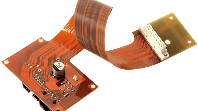
A Flexible PCB is a printed circuit board constructed on a flexible insulating substrate rather than the rigid fiberglass structure typically used for conventional FR-4 PCBs.
Flexible circuits commonly use polyimide or other specialized flexible dielectric materials. Copper conductors are formed on the flexible substrate and protected by coverlay or an appropriate flexible solder-mask system.
The fundamental advantage is mechanical flexibility.
Depending on the design, a Flex PCB can:
- Bend during installation
- Fold into compact spaces
- Conform to curved surfaces
- Connect moving components
- Support three-dimensional packaging
- Replace cables and multiple interconnects
However, not every flexible PCB is designed for continuous movement. Flexible circuits should be engineered and specified according to whether they are intended for static flexing during installation or dynamic flexing during operation.
IPC-6013 recognizes different flexible-board types and installation uses, including circuits designed to withstand flexing during installation and circuits intended for continuous flexing. (国际电信联盟)
What Is Flexible PCBA?
Flexible PCBA refers to the completed flexible circuit assembly after electronic components have been mounted and soldered onto the Flex PCB.
A flexible PCBA may combine:
- Flexible substrate
- Copper conductors
- Components
- Connectors
- Stiffeners
- Coverlay
- Surface finishes
- Shielding structures
- Mechanical reinforcement
Because flexible substrates are thinner and mechanically different from rigid boards, they require carefully controlled handling throughout assembly.
Common manufacturing concerns include:
- Substrate deformation
- Moisture absorption
- Solder paste alignment
- Component placement accuracy
- Reflow-induced warpage
- Copper fatigue
- Bend-radius limitations
- Component stress
- Connector reinforcement
Common Applications of Flex PCB Assembly
The ability to route electronic circuits through compact or moving structures makes Flex PCB Assembly useful across many industries.
Typical applications include:
- Smartphones
- Tablets
- Smartwatches
- Wearable electronics
- Cameras
- Automotive sensors
- ADAS modules
- Automotive displays
- LED lighting
- Medical instruments
- Portable medical devices
- Aerospace electronics
- Industrial automation
- Robotics
- IoT devices
- Communication equipment
Flexible PCB technology is particularly valuable when reducing cables and connectors can simplify mechanical integration.
Flex PCB vs. Rigid PCB vs. Rigid-Flex PCB
Selecting the right PCB structure affects product size, reliability, manufacturability, and total cost.
| Feature | Flex PCB | Rigid PCB | Rigid-Flex PCB |
|---|---|---|---|
| Base Material | Polyimide or other flexible materials | FR-4 or other rigid laminates | Combination of rigid and flexible materials |
| Flexibility | High | Very limited | Localized |
| Weight | Low | Moderate | Moderate |
| 3D Routing | Excellent | Limited | Excellent |
| Space Saving | Excellent | Moderate | Excellent |
| Mechanical Structure | Flexible | Rigid | Hybrid |
| Manufacturing Cost | Generally higher than standard rigid PCB | Generally lower | Generally higher |
| Best Applications | Moving or space-constrained electronics | Fixed electronic assemblies | Complex 3D electronic systems |
Flexible PCB
A Flex PCB is appropriate when the circuit must bend, fold, or fit into a constrained space.
Rigid PCB
A Rigid PCB is generally more economical for fixed electronic assemblies where flexibility is not required.
Rigid-Flex PCB
A Rigid-Flex PCB combines rigid areas for component mounting with flexible sections for interconnection.
Rigid-flex technology can reduce:
- Cable assemblies
- Connector count
- Mechanical interfaces
- Assembly complexity
- Installation space
For complex products, rigid-flex can provide a better overall system solution even though the initial PCB cost may be higher.
Flexible PCBA Materials
Material selection has a direct impact on flex PCB reliability, flexibility, electrical performance, thermal performance, and assembly yield.
Polyimide Substrate
Polyimide is one of the most widely used materials for flexible PCB construction because of its flexibility, dimensional stability, and thermal performance.
It is suitable for flexible circuits that need to withstand soldering processes and demanding operating environments.
The specific temperature rating and material construction should always be selected according to the manufacturer’s material data and the intended application.
Copper Foil
Copper forms the primary conductive layer of most flexible circuits.
Two common copper approaches are:
Electrodeposited (ED) copper: Often used where flexibility requirements are moderate.
Rolled Annealed (RA) copper: Frequently preferred for dynamic-flex applications because its grain structure can provide better resistance to repeated bending.
Copper thickness must be balanced between:
- Current-carrying capability
- Electrical resistance
- Mechanical flexibility
- Bend performance
- Manufacturing requirements
Adhesive and Adhesiveless Construction
Flexible circuits can use either adhesive-based or adhesiveless constructions.
Adhesive-based laminates can provide a cost-effective solution for many applications.
Adhesiveless flexible laminates can offer advantages in high-density applications, including reduced dielectric thickness and potentially improved dimensional and thermal behavior.
The appropriate construction depends on the application’s electrical, thermal, mechanical, and cost requirements.
Coverlay
Flexible circuits commonly use polyimide coverlay to protect copper conductors.
Coverlay provides protection against:
- Moisture
- Contamination
- Oxidation
- Mechanical damage
- Electrical exposure
The coverlay opening pattern should be carefully designed around solder pads and component locations.
Flexible Solder Mask
Some flexible circuits use flexible solder-mask systems instead of conventional coverlay or in combination with other protective structures.
The choice depends on:
- Circuit geometry
- Assembly process
- Bend requirements
- Component density
- Environmental conditions
Surface Finishes
Surface finishes improve copper protection and solderability.
Common finishes include:
- ENIG
- Immersion Silver
- Immersion Tin
- OSP
- Lead-free HASL where suitable
ENIG PCB is frequently selected for fine-pitch components because of its relatively flat surface and good solderability.
Stiffeners
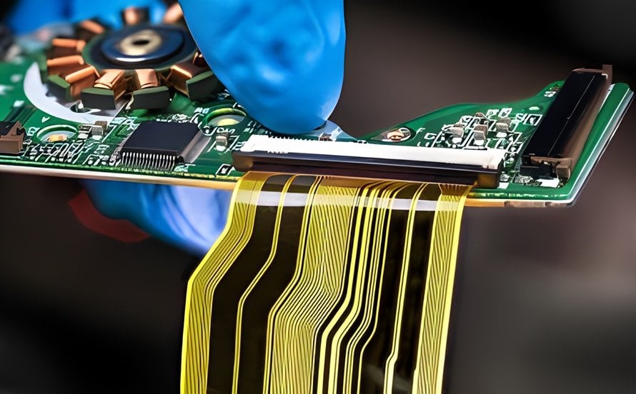
Flexible circuits frequently require stiffeners underneath connectors or component areas.
Common stiffener materials include:
- FR-4
- Polyimide
- Stainless steel
- Other application-specific reinforcement materials
Stiffeners can improve component mounting stability, connector insertion strength, and assembly handling.
They can also help keep components away from areas intended for repeated bending.
Advantages of Flex PCB Assembly
1. Compact and Space-Saving Design
One of the biggest benefits of Flexible PCB Assembly is its ability to fit into restricted spaces.
A flexible circuit can replace combinations of:
- Rigid PCBs
- Wires
- Cables
- Connectors
This allows manufacturers to create thinner and more compact electronic products.
2. Reduced Weight
Flexible circuits use thin substrates and can reduce the need for wiring harnesses and connectors.
This makes Flex PCB Assembly useful in:
- Aerospace equipment
- Drones
- Wearables
- Portable medical devices
- Automotive electronics
- Portable electronics
3. Greater Design Freedom
Flex PCBs allow engineers to develop three-dimensional circuit layouts that would be difficult to achieve with rigid boards.
They can be routed around mechanical structures and folded into the final enclosure.
4. Reduced Interconnections
A single flexible circuit can sometimes replace several rigid circuit boards and cable assemblies.
Fewer interconnections can mean:
- Fewer connectors
- Fewer cable assemblies
- Fewer potential connection points
- Simplified final assembly
5. Improved Mechanical Integration
Flexible circuits can conform to irregular shapes, making them suitable for products with moving or constrained mechanical structures.
6. Vibration and Shock Resistance
A properly designed flexible circuit can provide good resistance to vibration and mechanical movement.
However, actual reliability depends on materials, bend radius, copper structure, component placement, stiffeners, and the expected environmental conditions.
7. Support for Dynamic Applications
Flexible circuits can be designed for repeated motion when the appropriate materials and construction are selected.
Dynamic-flex applications require much more careful mechanical design than circuits that are flexed only during installation.
8. Potential System-Level Cost Reduction
Although the bare Flex PCB may cost more than a simple rigid PCB, the overall product can sometimes become less expensive because flexible circuits may eliminate:
- Cable assemblies
- Connectors
- Additional PCBs
- Manual wiring
- Mechanical fasteners
Therefore, Flex PCB cost should be evaluated at the system level, rather than by comparing the bare PCB price alone.
Flex PCB Assembly Process
The Flex PCB assembly process shares many steps with conventional PCB assembly, but additional mechanical and material controls are required.
1. PCB Design Verification
Before production, engineers should review:
- Component placement
- Bend zones
- Bend radius
- Copper routing
- Layer structure
- Stiffener locations
- Coverlay openings
- Connector areas
- Assembly clearances
A DFM/DFA review can identify manufacturing and assembly issues before production begins.
2. Material Preparation and Moisture Control
Flexible materials can absorb moisture during storage and transportation.
Depending on the material and storage conditions, controlled baking or drying may be required before assembly.
The actual temperature and duration should follow the material supplier’s requirements rather than applying a universal baking condition.
3. Carrier and Fixture Preparation
Because flexible circuits can deform under mechanical pressure, they are generally supported on dedicated carriers during SMT processing.
The carrier helps maintain:
- Flatness
- Alignment
- Dimensional stability
- Stencil registration
- Placement accuracy
Carrier design is particularly important for thin or large-format flex circuits.
4. Solder Paste Printing
Solder paste is applied through a stencil.
Important process variables include:
- Stencil thickness
- Aperture design
- Solder paste condition
- Printing pressure
- Printing speed
- Board support
- Alignment
Insufficient support can cause flexing during printing and result in solder-paste misregistration.
5. Component Placement
Automated pick-and-place machines position components onto the flexible circuit.
Vision systems verify component alignment and orientation.
Because flexible circuits are more susceptible to movement than rigid boards, stable carrier support is essential during this stage.
6. Reflow Soldering
The populated flex PCB passes through a controlled reflow profile to establish the solder joints.
The profile should be developed according to:
- Solder-paste chemistry
- Flexible substrate
- Copper thickness
- Component specifications
- Board thermal mass
- Carrier construction
The objective is to achieve adequate solder wetting while avoiding unnecessary thermal stress.
7. Automated Optical Inspection
After reflow, AOI can inspect:
- Component placement
- Polarity
- Solder bridges
- Missing components
- Tombstoning
- Visible solder defects
- Alignment
AOI provides rapid inspection and helps identify defects before electrical testing.
8. X-Ray Inspection
Automated X-Ray Inspection (AXI) is useful when the assembly includes hidden solder joints such as:
- BGA
- QFN
- Bottom-terminated components
X-ray inspection can help identify:
- Solder voids
- Insufficient solder
- Hidden bridging
- Open joints
- Internal solder defects
9. Electrical Testing
Depending on the product, electrical verification can include:
- Continuity testing
- Insulation testing
- Flying probe testing
- ICT
Flying probe is often useful for prototypes and low-volume products because it can reduce the need for custom test fixtures.
10. Functional Testing
Functional testing verifies that the completed flexible PCBA operates according to its intended specification.
Testing may involve:
- Communication interfaces
- Sensors
- Displays
- Power-management circuits
- Wireless functions
- Motors
- Control signals
The test strategy should be designed around the product’s actual functional and reliability requirements.
Reflow Soldering for Flex PCBs
Reflow soldering is one of the most important stages of flexible PCB assembly.
Because flexible substrates behave differently from rigid PCBs, manufacturers must carefully control both thermal and mechanical conditions.
Temperature Profile Optimization
The reflow profile should include controlled:
- Preheating
- Soak
- Reflow
- Cooling
The exact peak temperature depends on the solder paste, component requirements, PCB material, and assembly process.
For lead-free soldering, many SAC-based processes use peak temperatures in the range specified by the solder-paste supplier and component requirements.
The correct profile must be validated rather than relying on a single standard temperature.
Board Support During Reflow
Flexible circuits can sag or warp when heated.
Dedicated carriers or pallets can maintain the board’s geometry during reflow and reduce the risk of:
- Component misalignment
- Uneven soldering
- Board deformation
- Mechanical stress
Common Reflow Defects
Potential defects include:
- Tombstoning
- Solder bridging
- Insufficient solder
- Solder voiding
- Head-in-pillow defects
- Component misalignment
- Poor solder wetting
Process optimization can involve adjustments to:
- Stencil aperture design
- Solder-paste volume
- Placement accuracy
- Reflow profile
- Conveyor speed
- Board support
Post-Reflow Inspection
AOI and X-ray inspection can be used after reflow to verify solder-joint and component-placement quality before electrical testing.
IPC Standards for Flex PCB Assembly
Industry standards provide a framework for PCB design, fabrication, soldering, inspection, and quality management.
IPC-6013
IPC-6013 establishes qualification and performance requirements for flexible printed boards, including single-sided, double-sided, multilayer, and rigid-flex constructions. The standard also addresses flexible boards with stiffeners, plated-through holes, blind/buried vias, and HDI structures. (国际电信联盟)
It also distinguishes different performance classifications and installation uses, including circuits intended for installation flexing and continuous flexing. (国际电信联盟)
IPC-2223
IPC-2223 provides design guidance for flexible printed boards. It is used in conjunction with fabrication and performance specifications when developing flexible circuit designs.
Design considerations include:
- Bend areas
- Conductor routing
- Mechanical requirements
- Stiffeners
- Layer construction
IPC-A-610
IPC-A-610 provides acceptability criteria for electronic assemblies, including solder joints, component placement, workmanship, and other assembly characteristics.
The applicable acceptance class should be established according to the product’s intended application.
IPC J-STD-001
IPC J-STD-001 defines material, process, and acceptability requirements for soldered electrical and electronic assemblies. The current IPC publication available for reference is J-STD-001J, published in March 2024. It explicitly references IPC-2223 and IPC-6013 for flexible circuits and flexible-board fabrication. (国际电信联盟)
These standards should be treated as part of a larger quality framework rather than as independent guarantees of product reliability.
ISO 13485 for Medical Applications
For flexible PCB assemblies used in medical devices, manufacturers may need quality systems appropriate to the medical-device supply chain.
ISO 13485 is commonly relevant where the manufacturer is operating within a medical-device quality-management framework. The exact requirements depend on the product, regulatory pathway, and customer’s quality system.
How to Choose a Flex PCB Assembly Manufacturer
Choosing an experienced Flex PCB Assembly manufacturer is as important as selecting the PCB design itself.
Manufacturing Experience
Flexible circuits have different manufacturing challenges from rigid PCBs.
A capable supplier should understand:
- Thin flexible substrates
- Dynamic and static flex
- Bend-radius requirements
- Copper fatigue
- Stiffeners
- Coverlay
- Carrier tooling
- Fine-pitch component assembly
Engineering and DFM Support
A reliable manufacturer should be involved before production begins.
DFM/DFA support can evaluate:
- Bend zones
- Material selection
- Stiffener design
- Component placement
- Panelization
- Coverlay openings
- Assembly clearances
- Test access
- Manufacturing tolerances
Kingda provides DFM/DFA analysis, Gerber review, BOM verification, pick-and-place file verification, component availability analysis, and manufacturing-process optimization. (Kingda)
Manufacturing and Assembly Capabilities
When selecting a Flexible PCB Assembly supplier, evaluate whether the company can provide both PCB fabrication and assembly.
Kingda’s published capabilities include Flexible PCB Assembly, Rigid-Flex PCB Assembly, Multilayer PCB Assembly, HDI PCB Assembly, High-Frequency PCB Assembly, High-TG PCB Assembly, Heavy Copper PCB Assembly, and Controlled-Impedance PCB Assembly. (Kingda)
Quality Certifications and Systems
Kingda states that it holds IATF 16949:2016, ISO 13485:2016, and ISO 9001:2015 certifications, with additional qualifications including ISO 14001 and UL listed on its website. (Kingda)
For a specific project, customers should confirm which certification applies to the relevant manufacturing process and product.
Component Sourcing
For turnkey Flex PCBA, component availability can significantly affect the project schedule.
Kingda provides component procurement and BOM-related support, helping customers coordinate PCB fabrication, component sourcing, assembly, and testing through an integrated manufacturing workflow. (Kingda)
Inspection and Testing
A reliable manufacturer should have appropriate inspection capabilities, including:
- SPI
- AOI
- X-ray
- ICT
- Functional testing
- First Article Inspection
Kingda publishes capabilities including SPI, AOI, X-ray, ICT, FCT, and FAI, supporting inspection and testing for different PCB assembly requirements. (Kingda)
Why Choose Kingda for Flex PCB Assembly?
For customers looking for a reliable Flex PCB Assembly manufacturer, Kingda provides an integrated manufacturing solution covering the complete PCB and PCBA process.
Flexible PCB Manufacturing
Kingda supports Flex PCB and Rigid-Flex PCB manufacturing for products requiring compact, lightweight, or mechanically flexible interconnections. (Kingda)
One-Stop PCB and PCBA Services
Kingda integrates:
PCB Design Support → PCB Fabrication → Component Procurement → SMT/THT Assembly → Inspection → Testing → Final Assembly
This one-stop model simplifies supplier management and helps coordinate PCB fabrication and assembly requirements. (Kingda)
Prototype to Mass Production
Kingda supports prototype, low-volume, and mass-production PCB assembly, allowing customers to transition from engineering prototypes to production through one manufacturing partner. (Kingda)
Engineering Support
Kingda’s engineering team can support DFM/DFA review, BOM verification, Gerber review, component availability analysis, and production optimization. (Kingda)
Quality Management
Kingda reports IATF 16949, ISO 13485, and ISO 9001 certifications, supporting customers with automotive, medical, industrial, and other demanding electronic applications. (Kingda)
Best Practices for Flex PCB Assembly
A successful flexible PCBA project starts with a manufacturable design.
The following practices can reduce production risk:
1. Define the Flexing Requirement Early
Determine whether the circuit will flex once during installation or repeatedly during operation.
2. Establish the Bend Radius
Select an appropriate bend radius based on layer count, copper thickness, substrate construction, and dynamic-flex requirements.
3. Keep Components Away from Dynamic Bend Areas
Heavy or rigid components should generally be located outside areas that experience repeated flexing.
4. Use Appropriate Stiffeners
Use stiffeners around connectors and other mechanically sensitive regions where necessary.
5. Select the Correct Copper Type
RA copper is often preferred for demanding dynamic-flex applications, while ED copper may be appropriate for many static-flex applications.
6. Design the Carrier Early
Carrier and fixture design should be considered alongside the PCB design because they directly influence SMT printing and placement.
7. Confirm the Reflow Profile
Work with the assembly manufacturer to develop a thermal profile compatible with the solder paste, components, and flexible substrate.
8. Perform DFM/DFA Before Production
Early engineering review can help identify design problems before they create production delays.
Future Trends in Flex PCB Assembly
The demand for Flexible PCB Assembly is expected to continue as electronic products become thinner, lighter, and more integrated.
Higher-Density Flexible Circuits
Fine-line routing, microvias, HDI structures, and advanced multilayer flex designs are enabling more functionality in smaller spaces.
Rigid-Flex Integration
Rigid-Flex PCB technology can simplify three-dimensional electronic packaging by integrating multiple rigid sections with flexible interconnections.
Advanced Flexible Materials
Materials such as LCP are increasingly relevant to applications requiring combinations of flexibility, low moisture absorption, dimensional stability, and high-frequency performance.
Wearable and Medical Electronics
Flexible circuits are particularly attractive for wearable and medical products because they can conform to compact or irregular structures.
Automotive Electronics
EVs, ADAS, vehicle displays, camera systems, sensors, and connectivity modules are creating new opportunities for Flex PCB and Rigid-Flex PCB technology.
High-Speed Flexible Electronics
As flexible circuits are adopted in increasingly sophisticated electronic systems, greater attention will be required for:
- Controlled impedance
- Signal integrity
- Low-loss dielectric materials
- EMI/EMC
- High-density routing
Conclusion
Flex PCB Assembly has become an important manufacturing technology for modern electronics that require compact packaging, low weight, mechanical flexibility, and reliable electrical performance.
Flexible circuits can replace conventional cables, connectors, and multiple rigid boards, providing greater design freedom and improved system integration. They are now widely used in consumer electronics, automotive electronics, medical devices, aerospace systems, industrial automation, robotics, cameras, and wearable devices.
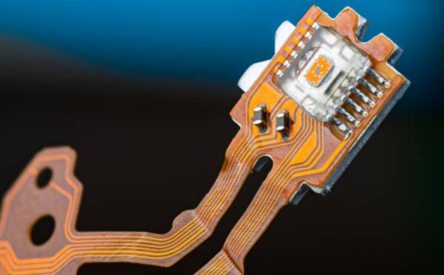
However, flexible PCB assembly requires more than simply mounting components onto a bendable circuit. Material selection, copper construction, bend radius, stiffeners, carrier design, solder-paste printing, component placement, reflow soldering, AOI, X-ray inspection, electrical testing, and DFM/DFA all contribute to final product reliability.
For companies looking for a reliable Flex PCB Assembly manufacturer, Kingda provides integrated flexible PCB and rigid-flex PCB manufacturing, SMT/THT assembly, component sourcing, DFM/DFA engineering, inspection, testing, prototyping, and production support. (Kingda)
With its one-stop PCB and PCBA manufacturing model, Kingda can support customers from Flex PCB prototypes and low-volume production to larger-scale manufacturing, helping turn complex flexible circuit designs into reliable production-ready electronic assemblies. (Kingda)