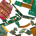
Miniaturization, higher functionality, and mechanical adaptability are three major trends shaping modern electronics. As electronic products become smaller, lighter, and more sophisticated, engineers increasingly need circuit boards that can withstand vibration, accommodate three-dimensional packaging, and fit into limited installation spaces.
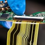
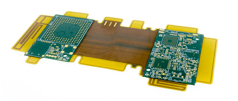
Rigid-Flex PCB Assembly provides an effective solution by combining the structural stability of rigid PCBs with the mechanical flexibility of flexible circuits. The rigid sections provide a stable platform for component mounting, while the flexible sections act as integrated interconnections that can bend, fold, and route through complex mechanical structures.
Unlike assemblies that rely on separate rigid boards, cables, and connectors, a well-designed Rigid-Flex PCB can integrate multiple circuit sections into a single electronic assembly. This can reduce interconnection points, simplify mechanical integration, save space, and improve overall system reliability.
Rigid-flex technology is widely used in medical devices, aerospace electronics, automotive systems, cameras, industrial automation, robotics, communications equipment, and advanced consumer electronics.
This guide explains what Rigid-Flex PCB Assembly is, how the manufacturing and assembly process works, how it compares with rigid and flexible PCB assembly, the main technical challenges, cost factors, quality-control requirements, and how Kingda supports rigid-flex PCB manufacturing from prototype to production.
What Is Rigid-Flex PCB Assembly?
Rigid-Flex PCB Assembly is the process of mounting and soldering electronic components onto a printed circuit board that combines rigid and flexible sections within one integrated structure.
The rigid portions are typically constructed from FR-4 or other rigid laminate systems, while the flexible sections generally use polyimide-based materials or other flexible dielectric materials.
The rigid sections provide:
- Mechanical support
- Stable component mounting
- Connector support
- Heat-spreading capability
- Suitable areas for dense component placement
The flexible sections provide:
- Bending capability
- Three-dimensional routing
- Compact interconnection
- Reduced wiring requirements
- Mechanical adaptability
The result is an integrated PCB structure that combines electrical functionality and mechanical design.
However, rigid-flex boards are more complex than conventional rigid PCBs because different materials can have different thermal, mechanical, and dimensional characteristics. These differences must be considered during PCB stackup design, lamination, routing, component placement, reflow soldering, and mechanical testing.
Why Use Rigid-Flex PCB Technology?
One of the main reasons engineers choose Rigid-Flex PCB technology is to simplify the overall electronic system.
A traditional electronic assembly may require:
Rigid PCB + Cable + Connector + Additional PCB
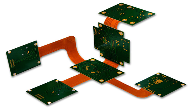
A rigid-flex architecture can sometimes combine these elements into:
One Integrated Rigid-Flex PCB Assembly
This can provide several advantages.
Reduced Connector Count
Replacing cable assemblies and connectors with integrated flexible interconnections can reduce the number of mechanical and electrical interfaces.
Space Optimization
Flexible sections can be routed around mechanical structures, allowing designers to use previously inaccessible areas.
Reduced Weight
Eliminating cables, connectors, and redundant board structures can reduce total system weight.
Improved Mechanical Integration
Rigid-flex circuits can be folded or bent during final assembly to match the product’s enclosure.
Potential Reliability Improvement
Fewer connectors and interconnections can reduce potential electrical and mechanical failure points.
Rigid PCB Assembly vs. Flex PCB Assembly vs. Rigid-Flex PCB Assembly
Understanding the differences between the three technologies is important when selecting the right PCB structure.
| Feature | Rigid PCB Assembly | Flex PCB Assembly | Rigid-Flex PCB Assembly |
|---|---|---|---|
| Main Material | FR-4 and rigid laminates | Polyimide and flexible materials | Rigid laminates + flexible materials |
| Flexibility | None | High | Localized |
| Mechanical Stability | Excellent | Moderate | Excellent |
| 3D Routing | Limited | Excellent | Excellent |
| Component Mounting | Easy | Requires additional support | Primarily on rigid sections |
| Space Saving | Moderate | Excellent | Excellent |
| Cable Reduction | Limited | High | High |
| Manufacturing Complexity | Lower | Higher | Highest |
| Typical Cost | Lowest | Higher | Highest |
| Typical Applications | General electronics | Compact and moving electronics | Advanced 3D electronic systems |
Standard Rigid PCB Assembly
Rigid PCBs are relatively straightforward to process because the board maintains a stable shape throughout solder paste printing, component placement, and reflow.
They are appropriate for fixed electronic assemblies where flexibility is not required.
Flexible PCB Assembly
Flexible PCB Assembly requires additional support because polyimide-based circuits can deform during manufacturing.
Dedicated carriers, pallets, or fixtures are often used to maintain flatness during stencil printing and component placement.
Rigid-Flex PCB Assembly
Rigid-Flex PCB Assembly combines the mechanical stability of rigid PCB sections with the flexibility of interconnecting regions.
This makes it particularly useful for products where:
- Components need stable mounting
- The circuit must bend during installation
- Space is limited
- Cable assemblies should be minimized
- Three-dimensional routing is required
The Full Rigid-Flex PCB Assembly Process
The assembly process follows many of the same fundamental steps used for SMT assembly, but rigid-flex products require additional controls for material compatibility, thermal expansion, transition-zone stress, and mechanical handling.
Phase 1: Material Preparation and Conditioning
Incoming Quality Control
Before assembly, the PCB and components should be checked against the approved manufacturing data.
Typical incoming checks include:
- PCB dimensions
- Layer structure
- Surface condition
- Surface finish
- Component specifications
- Quantity
- Packaging condition
Moisture Control
PCB laminate and flexible dielectric materials can absorb moisture during storage.
Depending on the material system and storage conditions, controlled drying or baking may be necessary before assembly.
This can reduce risks associated with:
- Delamination
- Blistering
- Soldering defects
- Moisture-related thermal damage
Baking parameters should follow the specifications of the PCB material and component manufacturers.
Surface Cleaning
The board should be clean and free from contamination that could interfere with soldering or electrical performance.
For rigid-flex products, special attention should also be given to flexible sections and transition areas to prevent mechanical or surface damage.
Phase 2: Solder Paste Printing and Component Placement
Solder Paste Printing
Solder paste is applied to designated component pads using a stainless-steel stencil.
Because the flexible sections can move or deform, manufacturing fixtures or rigid carriers may be used to support the board during printing.
Proper support helps maintain:
- Stencil alignment
- Paste deposition consistency
- Pad registration
- Board flatness
Component Placement
SMD components are placed onto the rigid sections using automated pick-and-place equipment.
High-precision vision systems can verify component orientation and placement.
Component placement should generally avoid dynamic flex zones unless the design specifically supports components in those regions.
Phase 3: Controlled Reflow Soldering
Reflow soldering is one of the most important stages of Rigid-Flex PCB Assembly.
Rigid and flexible portions may respond differently to heating because their material structures and thermal expansion characteristics differ.
Therefore, the reflow process needs to be carefully evaluated.
Gradual Heating
A controlled heating profile can help minimize thermal stress and reduce sudden expansion differences between materials.
Controlled Peak Temperature
The peak temperature must be compatible with:
- Solder paste
- Components
- PCB materials
- Flexible dielectric
- Coverlay
- Adhesives
The correct peak temperature should be established from the solder-paste and component manufacturer’s process windows rather than applying one fixed temperature to every rigid-flex PCB.
Thermal Uniformity
The assembly should be evaluated to ensure that rigid and flexible regions receive appropriate thermal exposure.
Controlled Cooling
Cooling rate can influence solder-joint formation and mechanical stress. Controlled cooling helps avoid unnecessary stress concentrations between dissimilar materials.
Phase 4: Post-Reflow Assembly and Inspection
Stiffeners and Reinforcement
Rigid-flex assemblies may require additional reinforcement around:
- Connectors
- Component areas
- Mounting holes
- Fold points
- Mechanical interfaces
Common stiffener materials include FR-4, polyimide, and stainless steel.
Through-Hole Component Assembly
Where THT components are required, selective soldering or other suitable soldering methods can be used.
The process should minimize unnecessary thermal exposure to flexible sections.
Depanelization
After assembly and inspection, the rigid-flex PCB panel is separated into individual assemblies using an appropriate depanelization method.
Mechanical stress should be minimized to prevent damage to flexible sections and transition zones.
AOI Inspection
Automated Optical Inspection (AOI) can inspect:
- Component placement
- Polarity
- Solder bridges
- Missing components
- Tombstoning
- Visible solder defects
X-Ray Inspection
X-Ray inspection is useful for hidden solder joints, particularly for:
- BGA
- QFN
- Bottom-terminated components
It can identify defects that are not visible through conventional optical inspection.
Electrical and Mechanical Testing
Rigid-flex PCB reliability cannot be evaluated only through visual inspection.
Depending on the product, testing may include:
Electrical Testing
- Continuity testing
- Insulation testing
- Flying probe
- ICT
- Functional testing
Mechanical Testing
- Bend testing
- Fold testing
- Flex-cycle testing
- Connector insertion testing
- Mechanical shock
- Vibration testing
Environmental Testing
Depending on the application:
- Thermal cycling
- High-temperature testing
- Humidity testing
- Chemical exposure
- EMC testing
The actual test plan should be established according to application requirements and applicable customer or industry specifications.
Key Technical Factors in Rigid-Flex PCB Manufacturing
1. Thermal Expansion Mismatch
One of the major challenges in rigid-flex manufacturing is the difference in thermal expansion between rigid and flexible materials.
FR-4 and polyimide do not respond identically to temperature changes.
Repeated thermal cycling can create mechanical stress in:
- Layer interfaces
- Copper conductors
- Adhesive layers
- Transition regions
- Solder joints
Therefore, material selection, stackup design, lamination, and thermal processing must be carefully coordinated.
2. Layer Bonding and Lamination
Rigid-flex boards contain multiple material systems that must remain securely bonded during manufacturing and operation.
Poor lamination or insufficient bonding can lead to:
- Delamination
- Layer separation
- Cracking
- Mechanical failure
Controlled lamination parameters and appropriate material combinations are essential.
3. Transition Zone Design
The rigid-to-flex transition zone is one of the most mechanically sensitive parts of a rigid-flex PCB.
Sharp geometric changes can concentrate stress.
Good design practices include:
- Smooth transition geometry
- Rounded copper features
- Avoiding unnecessary vias near bend zones
- Appropriate coverlay design
- Controlled copper distribution
- Proper bend radius
Transition-zone design should be reviewed during DFM rather than after fabrication.
4. Copper Thickness
Thicker copper provides improved current-carrying capability but generally reduces flexibility.
Thinner copper can improve flex performance but may limit current-carrying capacity.
Therefore, the copper thickness should be selected based on both:
Electrical Requirements + Mechanical Requirements
5. Bend Radius
The required minimum bend radius depends on:
- Number of flex layers
- Copper thickness
- Material type
- Static or dynamic flexing
- Expected flex cycles
Dynamic-flex designs require particular attention because repeated bending can cause copper fatigue.
Quality Control in Rigid-Flex PCB Assembly
A reliable Rigid-Flex PCB Assembly manufacturer should implement quality control throughout the entire process rather than relying only on final inspection.
Quality control can include:
Incoming Quality Control
Verification of PCB materials, components, and manufacturing data.
Process Inspection
Monitoring solder paste printing, placement, reflow, and assembly conditions.
AOI
Automated optical inspection for visible defects.
X-Ray
Inspection of hidden solder joints and internal assembly structures.
Electrical Testing
Verification of continuity, isolation, and functional performance.
Mechanical Testing
Evaluation of bend and mechanical durability according to the application.
Environmental Testing
Thermal and environmental testing when required.
Cost Factors in Rigid-Flex PCB Assembly
Rigid-Flex PCB Assembly generally costs more than conventional rigid PCB assembly because it requires more advanced materials, fabrication processes, tooling, handling, and inspection.
Major cost factors include:
Material Cost
Rigid-flex boards combine rigid and flexible materials, which can be more expensive than standard FR-4.
Layer Count
Increasing the number of rigid and flexible layers increases fabrication complexity.
Flexible Circuit Length and Shape
More complex flexible sections may require additional manufacturing steps.
Stiffeners and Reinforcement
Additional reinforcement adds both material and processing cost.
Specialized Tooling
Carrier fixtures and assembly tooling may be required to ensure stable component placement.
Inspection and Testing
X-ray, mechanical testing, environmental testing, and other specialized inspections can increase manufacturing cost.
Low Production Volume
Prototypes and low-volume orders often have higher unit costs because engineering, tooling, setup, and testing expenses are distributed across fewer units.
However, Rigid-Flex PCB cost should be evaluated at the system level.
A more expensive rigid-flex PCB may ultimately reduce total product cost by eliminating:
- Cable assemblies
- Connectors
- Multiple rigid boards
- Mechanical fasteners
- Manual wiring
Applications of Rigid-Flex PCB Assembly
Aerospace and Defense
Rigid-flex technology is well suited to aerospace systems where weight, reliability, vibration resistance, and packaging efficiency are critical.
Applications include:
- Avionics
- Navigation systems
- Communication systems
- Radar electronics
- Control systems
- Satellite electronics
Medical Electronics
Rigid-flex PCBs can provide compact and highly integrated interconnections for:
- Diagnostic equipment
- Imaging systems
- Portable medical equipment
- Surgical instruments
- Patient monitoring equipment
Automotive Electronics
Modern vehicles increasingly use compact electronic modules with complex three-dimensional packaging.
Rigid-flex PCBs can be used in:
- ADAS electronics
- Camera modules
- Instrument clusters
- Sensors
- Lighting
- Battery systems
- Vehicle control modules
Consumer Electronics
Applications include:
- Smartphones
- Cameras
- Wearables
- Foldable electronics
- Portable devices
- Compact computing equipment
Industrial Automation and Robotics
Rigid-flex circuits can simplify interconnections in:
- Robotic systems
- Sensors
- Motion-control equipment
- Industrial cameras
- Measurement systems
How to Choose a Rigid-Flex PCB Assembly Manufacturer
Selecting a capable Rigid-Flex PCB manufacturer and assembly supplier is critical because rigid-flex products require both PCB fabrication expertise and assembly engineering.
1. Evaluate Rigid-Flex Manufacturing Experience
Ask whether the manufacturer has experience with:
- Multilayer rigid-flex
- Fine-line flexible circuits
- Stiffeners
- Blind and buried vias
- Microvias
- Controlled impedance
- Dynamic flex
- Complex transition zones
2. Evaluate DFM and DFA Support
Early engineering involvement can help prevent costly manufacturing problems.
The manufacturer should be able to review:
- Stackup
- Bend zones
- Transition regions
- Copper distribution
- Component placement
- Stiffener design
- Coverlay
- Panelization
- Test access
3. Check Assembly Capabilities
Look for capabilities including:
- SMT assembly
- THT assembly
- BGA assembly
- Fine-pitch assembly
- Reflow soldering
- Selective soldering
- AOI
- X-ray
- ICT
- Functional testing
4. Evaluate Component Sourcing
For turnkey projects, component availability can affect both cost and delivery.
An integrated supplier that can handle PCB fabrication, component sourcing, and assembly can simplify project management.
5. Verify Quality Systems
The applicable certifications should match the product and target market.
For demanding applications, customers may need quality systems such as:
- ISO 9001
- IATF 16949
- ISO 13485
along with appropriate IPC fabrication and assembly standards.
Kingda Rigid-Flex PCB Manufacturing and Assembly Solutions
For companies looking for a reliable Rigid-Flex PCB Assembly manufacturer, Kingda provides an integrated PCB and PCBA manufacturing solution.
Kingda’s published capabilities include Rigid-Flex PCB Assembly, Flexible PCB Assembly, HDI PCB Assembly, Multilayer PCB Assembly, High-Frequency PCB Assembly, High-TG PCB Assembly, Heavy Copper PCB Assembly, and Controlled-Impedance PCB Assembly. (gopcba.com)
One-Stop Rigid-Flex PCB Manufacturing
Kingda can coordinate the complete manufacturing process:
PCB Design Support → Rigid-Flex PCB Fabrication → Component Sourcing → SMT/THT Assembly → AOI/X-Ray → Electrical Testing → Functional Testing → Final Inspection
This integrated workflow can simplify supplier management and improve communication between PCB fabrication and assembly teams. (gopcba.com)
DFM/DFA Engineering Support
Rigid-flex projects often require more engineering review than standard rigid PCBs.
Kingda provides:
- DFM review
- DFA analysis
- Gerber review
- BOM verification
- Pick-and-place file review
- Component availability analysis
- Stackup evaluation
- Manufacturing process optimization
These services help identify potential manufacturing issues before production. (gopcba.com)
Prototype to Mass Production
Kingda supports PCB prototypes, low-volume production, pilot production, and volume manufacturing, allowing customers to develop rigid-flex products through different stages without necessarily changing manufacturing suppliers. (gopcba.com)
Advanced Inspection and Testing
Kingda’s published PCBA capabilities include:
- SPI
- AOI
- X-ray inspection
- ICT
- FCT
- First Article Inspection
These inspection methods can be selected according to the complexity and reliability requirements of each rigid-flex assembly. (gopcba.com)
Quality Management
Kingda reports IATF 16949, ISO 13485, and ISO 9001 certifications, supporting customers across automotive, medical, industrial, and other demanding electronic applications. (gopcba.com)
Component Procurement and Supply Chain Support
Kingda provides component sourcing and BOM support, helping customers coordinate PCB fabrication, component procurement, assembly, and testing through an integrated manufacturing workflow. (gopcba.com)
Best Practices for Rigid-Flex PCB Design and Assembly
To improve manufacturing yield and long-term reliability:
Design the Transition Zone Carefully
The rigid-to-flex transition should avoid abrupt geometric changes and unnecessary mechanical stress.
Define Bend Requirements Early
Specify whether the flexible section is intended for:
- Installation bending
- Static bending
- Repeated dynamic bending
Keep Heavy Components Away from Dynamic Flex Areas
Components and solder joints should generally be placed on structurally stable rigid sections unless the design specifically supports component placement in flex zones.
Select Materials Based on the Application
Consider:
- Temperature
- Frequency
- Mechanical movement
- Chemical exposure
- Current requirements
- Flex-cycle requirements
Perform DFM/DFA Before Fabrication
A complete engineering review can identify potential problems before costly tooling and production are initiated.
Define Testing Before Production
Test requirements should be established in advance for:
- Electrical performance
- Mechanical durability
- Thermal cycling
- Environmental performance
- Functional operation
Conclusion
Rigid-Flex PCB Assembly combines the mechanical stability of rigid PCBs with the packaging flexibility of flexible circuits, making it an important technology for modern electronics that require compact size, three-dimensional routing, reduced wiring, and reliable mechanical integration.
Compared with conventional rigid PCB assemblies, rigid-flex designs can reduce connectors and cables while improving system-level packaging efficiency. Compared with fully flexible circuits, the rigid sections provide a more stable platform for component mounting and thermal management.

However, rigid-flex PCB manufacturing and assembly are more technically demanding. Material selection, thermal expansion, layer bonding, transition-zone design, bend radius, copper thickness, stiffeners, reflow control, AOI, X-ray, electrical testing, and mechanical validation all contribute to final product reliability.
For customers seeking a reliable Rigid-Flex PCB manufacturer and Rigid-Flex PCB Assembly supplier, Kingda provides integrated fabrication and assembly services supported by DFM/DFA engineering, component sourcing, SMT/THT assembly, inspection, testing, and scalable production. (gopcba.com)
From rigid-flex PCB prototypes and low-volume production to volume manufacturing, Kingda can support customers developing advanced electronic products for automotive, medical, aerospace, industrial, communication, and consumer applications. (gopcba.com)