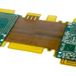
As electronic products become smaller, lighter, and more highly integrated, conventional rigid circuit boards are often unable to satisfy increasingly complex packaging and interconnection requirements. Rigid-Flex PCB technology combines rigid circuit sections with flexible circuit regions, allowing engineers to integrate electrical connections into compact and three-dimensional mechanical structures.
Compared with conventional rigid PCBs, Rigid-Flex PCBs provide greater packaging freedom, reduced wiring complexity, fewer connectors, and improved mechanical integration. These advantages make rigid-flex technology increasingly valuable in automotive electronics, medical devices, aerospace systems, cameras, wearable devices, robotics, industrial controls, telecommunications, and other high-density electronic applications.
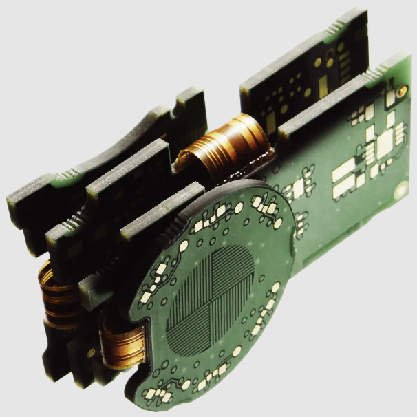
However, designing and manufacturing a rigid-flex circuit board is considerably more complex than producing a conventional rigid PCB. Engineers must account for material compatibility, thermal expansion, bend radius, rigid-to-flex transition areas, layer stack-up, signal integrity, lamination, component placement, and long-term mechanical reliability.
This guide explains what a Rigid-Flex PCB is, how rigid-flex stack-ups are designed, how rigid-flex PCBs are manufactured, the differences between rigid-flex and traditional rigid boards, the major design and manufacturing challenges, and how Kingda supports rigid-flex PCB fabrication and assembly.
What Is a Rigid-Flex PCB?
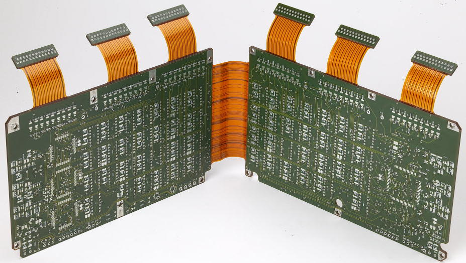
A Rigid-Flex PCB is a printed circuit board that integrates rigid and flexible circuit technologies into a single interconnected structure.
The rigid sections are commonly manufactured using materials such as FR-4, while the flexible portions generally use polyimide (PI) or other specialized flexible dielectric materials.
The rigid sections provide:
- Mechanical stability
- Component mounting areas
- Connector support
- Heat dissipation
- High-density component placement
The flexible sections provide:
- Bending and folding capability
- Three-dimensional routing
- Compact interconnection
- Reduced cable requirements
- Mechanical adaptability
By combining these structures into one PCB, designers can replace some conventional cable-and-connector assemblies with an integrated circuit solution.
A well-designed Rigid-Flex PCB can therefore reduce system volume, simplify mechanical assembly, and improve electrical and mechanical integration.
Why Use Rigid-Flex PCB Technology?
The primary value of Rigid-Flex PCB technology is its ability to combine the best characteristics of rigid and flexible circuits.
A conventional system may require multiple rigid boards connected with cables and connectors. A rigid-flex architecture can integrate several of these functions into one PCB assembly.
Potential advantages include:
Reduced Connector Count
Flexible sections can directly connect different rigid circuit areas, reducing the number of external connectors and cable assemblies.
Better Space Utilization
The flexible section can be folded around components or routed through compact mechanical structures.
Lower System Weight
Reducing cables, connectors, and additional PCB assemblies can lower total system weight.
Improved Mechanical Integration
The PCB can be shaped to match the enclosure and mechanical structure of the final product.
Potential Reliability Improvement
Fewer mechanical and electrical interconnections can reduce the number of potential connection failure points.
Simplified Final Assembly
An integrated rigid-flex structure can eliminate some cable routing and connector installation operations.
Rigid-Flex PCB Stack-Up
The Rigid-Flex PCB stack-up is one of the most important design elements because it determines electrical performance, mechanical flexibility, manufacturability, and reliability.
A basic flexible section may contain one or two copper layers separated from or supported by a flexible dielectric such as polyimide.
A more advanced rigid-flex PCB can contain several rigid layers combined with one or more flexible layer structures.
A typical construction may include:
Rigid Multilayer Section → Rigid-to-Flex Transition → Flexible Circuit Section → Rigid-to-Flex Transition → Rigid Multilayer Section
The exact stack-up depends on:
- Number of signal layers
- Power and ground requirements
- Controlled impedance requirements
- Bending requirements
- Component density
- Board thickness
- Thermal requirements
- Manufacturing process
Flexible Layer Construction
Flexible portions commonly use:
- Copper foil
- Polyimide dielectric
- Coverlay
- Adhesive or adhesiveless laminate
- Surface finish
- Optional stiffeners
Rigid Layer Construction
Rigid sections may use:
- FR-4 core
- Prepreg
- Copper foil
- Solder mask
- Surface finish
- Stiffeners or mechanical reinforcement
Rigid-to-Flex Transition Area
The transition between rigid and flexible regions requires particular attention.
Sudden changes in:
- Layer thickness
- Copper density
- Mechanical geometry
- Material structure
can create stress concentrations.
A properly designed transition zone should therefore use smooth geometry and appropriate mechanical support.
Rigid-Flex PCB vs. Traditional Rigid PCB
| Feature | Rigid-Flex PCB | Traditional Rigid PCB |
|---|---|---|
| Structure | Rigid + flexible sections | Rigid structure only |
| Materials | FR-4 + PI/flexible materials | FR-4 or other rigid materials |
| Flexibility | Localized | None |
| 3D Routing | Excellent | Limited |
| Connector Reduction | High potential | Limited |
| Space Utilization | Excellent | Moderate |
| Manufacturing Complexity | High | Lower |
| Material Cost | Higher | Generally lower |
| Design Complexity | High | Moderate |
| Typical Applications | Aerospace, medical, automotive, compact electronics | Consumer, industrial, control electronics |
The higher manufacturing cost of a rigid-flex PCB can be justified when the design benefits from reduced cables, fewer connectors, lower system weight, or improved mechanical integration.
Rigid-Flex PCB Manufacturing Process
Because a rigid-flex PCB combines flexible and rigid structures, its manufacturing process requires capabilities from both flexible PCB fabrication and rigid multilayer PCB manufacturing.
A typical process includes several major stages.
1. PCB Design and Engineering Review
The process begins with detailed PCB design and manufacturability analysis.
Engineers evaluate:
- Layer stack-up
- Bend zones
- Bend radius
- Rigid-to-flex transitions
- Copper distribution
- Via structures
- Component placement
- Stiffener locations
- Coverlay openings
- Impedance requirements
- Mechanical dimensions
A comprehensive DFM/DFA review at this stage can prevent manufacturing problems later.
2. Material Selection
Material selection has a significant impact on rigid-flex PCB reliability.
Common materials include:
- FR-4
- Polyimide
- Flexible copper laminates
- High-Tg materials
- Low-loss materials
- Adhesiveless flex materials
- Prepreg
- Coverlay
Material combinations should be evaluated for:
- Coefficient of thermal expansion
- Adhesion
- Flexibility
- Thermal resistance
- Electrical performance
- Mechanical reliability
3. Flexible Circuit Fabrication
The flexible section is manufactured using processes similar to those used for flexible PCBs.
Depending on the design, processes may include:
- Copper imaging
- Etching
- Drilling or laser drilling
- Plating
- Coverlay application
- Surface finishing
For high-density designs, microvias and HDI structures may be incorporated into the flexible section.
4. Rigid PCB Fabrication
The rigid sections are manufactured using conventional multilayer PCB processes.
Typical operations include:
- Inner-layer imaging
- Etching
- Lamination
- Mechanical drilling
- Laser drilling where required
- Copper plating
- Outer-layer imaging
- Solder mask
- Surface finish
5. Lamination
The rigid and flexible sections are assembled into the final rigid-flex structure through controlled lamination.
The lamination process must control:
- Temperature
- Pressure
- Heating rate
- Cooling rate
- Material alignment
- Resin flow
- Layer registration
Improper lamination may lead to:
- Delamination
- Voids
- Misalignment
- Layer separation
- Mechanical stress
6. Drilling and Via Formation
Depending on the design, rigid-flex boards can incorporate:
- Through vias
- Blind vias
- Buried vias
- Microvias
- Via-in-pad structures
The via structure should be designed carefully around the flexible areas to maintain mechanical reliability.
7. Surface Finishing
Common surface finishes include:
- ENIG
- ENEPIG
- OSP
- Immersion tin
- Immersion silver
- Lead-free HASL
- Selective gold
Surface finish selection should be based on component package, assembly process, electrical requirements, reliability, and cost.
What Are the Main Challenges in Rigid-Flex PCB Design?
1. Complex Layout and 3D Routing
One of the biggest advantages of a rigid-flex circuit is also one of its biggest design challenges.
Unlike a conventional rigid PCB that can be considered primarily as a two-dimensional layout, a rigid-flex product must also be evaluated as a three-dimensional mechanical structure.
Engineers need to consider:
- How the flexible section bends
- Where the PCB folds
- Minimum bend radius
- Component clearance
- Mechanical interference
- Connector position
- Final assembly sequence
2. Thermal Expansion Mismatch
FR-4 and polyimide have different thermal properties.
During manufacturing and operation, repeated temperature changes can cause differences in expansion and contraction.
This may generate mechanical stress at:
- Rigid-flex transitions
- Copper interfaces
- Lamination interfaces
- Solder joints
Therefore, material selection and thermal-process optimization are extremely important.
3. Transition-Zone Reliability
The rigid-to-flex transition zone is mechanically sensitive.
Sharp corners, abrupt copper changes, or poorly designed coverlay structures may increase stress concentration.
Designers should consider:
- Smooth transition geometry
- Rounded copper features
- Appropriate copper distribution
- Controlled bend locations
- Adequate coverlay
- Appropriate stiffeners
4. Material Compatibility
The materials used in the rigid and flexible sections must be compatible in terms of:
- Thermal expansion
- Adhesion
- Lamination temperature
- Mechanical properties
- Electrical characteristics
Improper material combinations can result in delamination or long-term reliability problems.
5. Signal Integrity
High-speed rigid-flex designs introduce additional challenges because the signal path crosses different material structures.
Engineers need to consider:
- Controlled impedance
- Dielectric thickness
- Copper thickness
- Reference planes
- Return paths
- Crosstalk
- Connector transitions
For high-speed or RF applications, rigid-flex stack-up design should be reviewed together with the PCB manufacturer.
Rigid-Flex PCB Assembly Challenges
Fabricating a rigid-flex PCB is only part of the process. Component assembly also requires additional manufacturing controls.
Solder Paste Printing
Flexible regions can deform under pressure.
Appropriate carrier or fixture support may therefore be necessary during stencil printing.
The support system should maintain:
- Board flatness
- Stencil alignment
- Printing accuracy
- Stable solder paste deposition
Component Placement
Components are generally placed on rigid sections whenever possible.
High-precision placement equipment and vision alignment systems can improve:
- Component positioning
- Orientation
- Fine-pitch assembly
- BGA alignment
Reflow Soldering
The different thermal characteristics of rigid and flexible areas can create challenges during reflow.
A controlled thermal profile should be developed based on:
- Solder paste
- Components
- PCB materials
- Copper distribution
- Board structure
The process should minimize unnecessary thermal and mechanical stress.
Inspection
A complete Rigid-Flex PCB Assembly quality system can include:
- SPI
- AOI
- X-ray inspection
- Visual inspection
- ICT
- Functional testing
For BGA and hidden solder joints, X-ray inspection provides additional verification.
Quality Control and Testing
Rigid-flex PCBs often require more comprehensive validation than standard rigid PCBs.
Testing may include:
Electrical Testing
- Continuity
- Insulation
- Flying probe
- ICT
- Functional testing
Mechanical Testing
- Bend testing
- Flex-cycle testing
- Connector insertion testing
- Mechanical shock
- Vibration
Environmental Testing
Depending on the application:
- Thermal cycling
- High-temperature testing
- Humidity testing
- Chemical resistance
- EMC testing
The specific test plan should be defined according to the application and customer requirements.
Cost Factors of Rigid-Flex PCBs
Rigid-Flex PCB manufacturing generally costs more than conventional rigid PCB production.
Major cost factors include:
Materials
Rigid-flex boards use multiple material systems, such as FR-4, polyimide, copper, coverlay, prepreg, and stiffeners.
Manufacturing Complexity
Rigid-flex requires more complex fabrication, lamination, alignment, and handling.
Layer Count
Increasing the number of rigid and flexible layers increases manufacturing complexity and material consumption.
Special Tooling
Carriers and fixtures may be required for assembly.
Inspection and Testing
Advanced inspection such as AOI and X-ray, together with mechanical and environmental tests where required, adds cost.
Production Volume
Rigid-flex prototypes and low-volume production typically have higher unit costs because engineering and tooling expenses are spread over fewer units.
However, the correct cost comparison should be performed at the system level.
A rigid-flex solution may eliminate:
- Cables
- Connectors
- Additional PCBs
- Wiring
- Mechanical mounting parts
This can offset some of the higher PCB fabrication cost.
Applications of Rigid-Flex PCB
Automotive Electronics
Automotive rigid-flex PCBs can be used in:
- ADAS modules
- Camera systems
- Instrument clusters
- Sensors
- Lighting
- Battery electronics
- Vehicle control modules
The combination of flexibility and structural stability is particularly useful for compact vehicle electronic modules.
Aerospace and Defense
Rigid-flex technology is valuable in aerospace because it can reduce:
- Weight
- Wiring
- Connectors
- Installation volume
Potential applications include:
- Avionics
- Navigation
- Communication
- Radar
- Satellite electronics
- Control systems
Medical Electronics
Rigid-flex boards can support compact and mechanically integrated medical equipment.
Applications include:
- Diagnostic instruments
- Imaging systems
- Portable medical equipment
- Surgical electronics
- Monitoring systems
Consumer Electronics
Applications include:
- Smartphones
- Wearables
- Cameras
- Foldable devices
- Portable computers
- Compact electronic equipment
Industrial and Robotic Systems
Rigid-flex circuits can simplify wiring in:
- Robotics
- Industrial cameras
- Sensors
- Motion-control equipment
- Measurement systems
How to Choose a Rigid-Flex PCB Manufacturer
Selecting the right Rigid-Flex PCB manufacturer is critical because not every PCB factory has the necessary flexible-circuit manufacturing and assembly capabilities.
Manufacturing Experience
Look for experience with:
- Multilayer rigid-flex PCBs
- Flexible circuits
- Microvias
- Blind and buried vias
- Fine-line routing
- Controlled impedance
- Stiffeners
- Complex transition zones
Engineering Capability
A capable supplier should be able to assist with:
- DFM
- DFA
- Stack-up design
- Material selection
- Bend-radius evaluation
- Transition-zone design
- Component placement
- Mechanical integration
PCB Assembly Capability
The manufacturer should ideally provide:
- SMT assembly
- THT assembly
- BGA assembly
- Reflow soldering
- Selective soldering
- AOI
- X-ray
- ICT
- Functional testing
Supply Chain Capability
For turnkey projects, evaluate:
- BOM management
- Component sourcing
- Component availability
- Alternative components
- Incoming inspection
- Traceability
Quality Management
Depending on the end application, relevant quality systems may include:
- ISO 9001
- IATF 16949
- ISO 13485
- IPC fabrication and assembly standards
Kingda Rigid-Flex PCB Manufacturing and Assembly Advantages
For companies looking for a reliable Rigid-Flex PCB manufacturer and Rigid-Flex PCB Assembly supplier, Kingda provides an integrated PCB and PCBA manufacturing solution.
Kingda’s published PCB assembly capabilities include Rigid-Flex PCB Assembly, Flexible PCB Assembly, HDI PCB Assembly, Multilayer PCB Assembly, High-Frequency PCB Assembly, High-TG PCB Assembly, Heavy Copper PCB Assembly, and Controlled-Impedance PCB Assembly. (gopcba.com)
One-Stop PCB and PCBA Manufacturing
Kingda can coordinate the manufacturing process from:
PCB Design Support → PCB Fabrication → Component Sourcing → SMT/THT Assembly → Inspection → Testing → Final Assembly
This integrated workflow can reduce supplier coordination and simplify project management. (gopcba.com)
DFM and DFA Engineering Support
Rigid-flex designs require more detailed engineering review than conventional rigid PCBs.
Kingda provides support including:
- DFM analysis
- DFA analysis
- Gerber review
- BOM verification
- Pick-and-place file verification
- Component availability analysis
- Stack-up evaluation
- Manufacturing process optimization
These services can help detect production issues before fabrication and reduce unnecessary design iterations. (gopcba.com)
Advanced PCB Technology
Kingda supports a broad range of advanced PCB structures, including:
- Rigid-Flex PCB
- Flexible PCB
- HDI PCB
- Multilayer PCB
- High-frequency PCB
- High-speed PCB
- Heavy copper PCB
- High-TG PCB
- Metal-core PCB
- Controlled-impedance PCB
This enables customers to use one manufacturing partner for different PCB technologies as their product requirements evolve. (gopcba.com)
Prototype to Mass Production
Kingda supports PCB prototyping, low-volume production, pilot production, and volume manufacturing.
This allows customers to transition from engineering prototypes to production without necessarily changing manufacturing suppliers. (gopcba.com)
Component Sourcing
Kingda provides component sourcing and BOM support to help customers coordinate procurement and production within one manufacturing workflow. (gopcba.com)
Inspection and Testing
Kingda’s published PCBA capabilities include:
- SPI
- AOI
- X-ray inspection
- ICT
- FCT
- First Article Inspection
The appropriate inspection and testing combination can be selected according to the PCB design, component technology, and application requirements. (gopcba.com)
Quality Management
Kingda reports IATF 16949, ISO 13485, and ISO 9001 certifications, providing quality-management systems for automotive, medical, industrial, and other demanding electronic applications. (gopcba.com)
Conclusion
Rigid-Flex PCB technology provides an effective solution for modern electronic products that require compact packaging, three-dimensional routing, mechanical adaptability, and reliable electrical interconnection.
Compared with conventional rigid PCBs, rigid-flex circuits offer greater design freedom and can reduce cables and connectors. Compared with fully flexible PCBs, the rigid sections provide stable areas for component mounting and mechanical support.
However, the benefits of Rigid-Flex PCB Assembly come with greater manufacturing complexity. Material compatibility, thermal expansion, layer bonding, transition-zone design, bend radius, copper thickness, lamination, component placement, reflow soldering, inspection, and mechanical testing all influence long-term reliability.
Choosing an experienced Rigid-Flex PCB manufacturer is therefore critical to a successful project.
Kingda provides an integrated solution covering Rigid-Flex PCB manufacturing, Flex PCB manufacturing, PCB assembly, component sourcing, DFM/DFA engineering, AOI, X-ray inspection, electrical testing, prototyping, and volume production. (gopcba.com)
For customers developing automotive, aerospace, medical, industrial, communication, and consumer electronics, Kingda can support the transition from complex rigid-flex PCB designs to reliable production-ready assemblies.