LiDAR PCB vs. Millimeter Wave Radar PCB: Differences, Features, and Applications
Introduction to LiDAR PCB and Millimeter Wave Radar PCB

With the rapid development of autonomous driving, advanced driver assistance systems (ADAS), intelligent transportation, and industrial automation, sensing technologies such as LiDAR and millimeter wave radar have become increasingly important. As the core carrier for electronic components and signal transmission, the LiDAR PCB and Millimeter Wave Radar PCB directly affect the performance, accuracy, and reliability of these sensing systems.
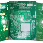
A LiDAR PCB (Light Detection and Ranging Printed Circuit Board) is a specialized circuit board used in laser radar systems. It supports laser emission, optical signal reception, data processing, and communication functions. Unlike traditional passive detection methods such as cameras that rely on ambient light, LiDAR uses an active detection method by transmitting laser pulses and measuring the time required for reflected signals to return. Based on this time-of-flight principle, the system can accurately calculate the distance, position, and shape of surrounding objects.
Kingda provides high-performance PCB manufacturing solutions for advanced sensing applications, including LiDAR PCB, automotive radar PCB, and other high-reliability electronic circuit boards. Through advanced manufacturing technology and strict quality control, Kingda helps customers achieve stable and reliable PCB performance in demanding environments.
Key Features of LiDAR PCB
1. High Precision PCB Manufacturing
The accuracy of a LiDAR system is highly dependent on the manufacturing precision of its circuit board. Since LiDAR requires extremely accurate signal processing and timing control, the LiDAR PCB must meet strict requirements in terms of layer alignment, drilling accuracy, impedance control, and dimensional stability.
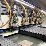
During manufacturing, advanced PCB fabrication technologies are applied, including precision imaging, high-accuracy CNC drilling, automated optical inspection (AOI), and strict process control. These technologies help ensure:
- Accurate circuit pattern formation
- Precise via and microvia positioning
- Stable PCB thickness
- Reliable electrical performance
- Improved signal transmission accuracy
For high-performance LiDAR applications, HDI PCB technology is often adopted to achieve higher wiring density and compact design requirements.
2. High-Speed Signal Transmission Capability
LiDAR systems need to process large amounts of three-dimensional environmental data in real time. Therefore, the PCB must provide excellent high-speed signal transmission capability with minimal signal loss and interference.
A high-performance LiDAR PCB design requires:
- Optimized high-speed routing
- Controlled impedance design
- Reduced signal reflection and transmission loss
- Proper power distribution design
- Effective electromagnetic interference (EMI) control
By optimizing PCB layer structures and signal routing, manufacturers can improve data transmission efficiency and ensure stable operation of LiDAR sensors.
3. High Reliability and Long-Term Stability
LiDAR systems are often used in automotive and industrial environments where continuous operation is required. Therefore, reliability is one of the most important requirements for LiDAR circuit boards.
High-reliability PCB manufacturing focuses on preventing:
- Open circuits
- Short circuits
- Signal distortion
- Delamination
- Thermal stress failures
- Mechanical deformation
Kingda applies strict quality management throughout PCB production, including material selection, lamination control, electrical testing, and reliability inspection, ensuring that LiDAR PCB solutions maintain stable performance under harsh operating conditions.
4. Multilayer PCB Structure Design
To meet the complex electrical requirements of LiDAR systems, multilayer structures are commonly used in LiDAR PCB design.
A multilayer PCB provides several advantages:
- Higher circuit density
- Better signal integrity
- Reduced electromagnetic interference
- Improved power and grounding design
- Separation of analog, digital, and power circuits
When designing multilayer radar and sensor PCBs, engineers need to carefully control parameters such as:
- PCB thickness
- Copper thickness
- Layer stack-up
- Dielectric materials
- Transmission line structures
Proper multilayer design ensures excellent electrical performance and long-term reliability.
Differences Between LiDAR PCB and Millimeter Wave Radar PCB
Although both LiDAR and millimeter wave radar are important sensing technologies for autonomous systems, their operating principles and PCB requirements are different.
1. Working Principle Differences
LiDAR System
LiDAR uses laser beams to detect objects. The system calculates distance by measuring the time difference between emitted laser pulses and reflected signals.
Advantages of LiDAR include:
- Extremely high measurement accuracy
- High spatial resolution
- Excellent object recognition capability
- Ability to generate detailed 3D point cloud information
However, LiDAR performance can be affected by environmental conditions such as:
- Heavy rain
- Fog
- Dust
- Smoke
- Snow
Because laser wavelengths are easily influenced by atmospheric conditions, detection distance and accuracy may decrease in severe weather.
Millimeter Wave Radar System
Millimeter wave radar uses electromagnetic waves, usually operating in frequency bands such as 24GHz, 77GHz, or 79GHz, to detect object distance, speed, and movement direction.
Compared with LiDAR, millimeter wave radar provides:
- Better weather resistance
- Longer detection distance
- Stronger penetration capability
- Better performance in rain, fog, and darkness
Therefore, Millimeter Wave Radar PCB requires excellent high-frequency characteristics, low-loss materials, and precise impedance control.
Comparison of LiDAR, Millimeter Wave Radar, and Camera Sensors
Resolution Performance
- Camera systems generally provide the highest image resolution.
- LiDAR offers excellent 3D spatial resolution.
- Millimeter wave radar has lower resolution but provides reliable distance and speed information.
Environmental Adaptability
- Millimeter wave radar provides the best performance under harsh weather conditions.
- Cameras may be affected by lighting and visibility.
- LiDAR performance can decrease in fog, rain, or dust environments.
Object Speed Detection
- Millimeter wave radar performs best in velocity measurement.
- LiDAR and cameras can also track object movement but may require more complex processing.
Object Height Detection
- LiDAR provides superior height and 3D structure detection.
- Cameras provide moderate performance.
- Millimeter wave radar has relatively limited height recognition capability.
Object Classification Capability
- Cameras and LiDAR provide excellent object recognition.
- Millimeter wave radar has weaker object classification ability but performs well in distance and speed measurement.
PCB Requirements for Automotive Radar and Sensor Applications
As autonomous driving technology continues to evolve, radar and sensor systems require increasingly advanced PCB solutions.
Key PCB technologies include:
High Frequency PCB
Used for millimeter wave radar systems, requiring low dielectric loss materials, stable electrical properties, and accurate impedance control.
HDI PCB
Provides high-density wiring capability for compact sensor modules and advanced electronic systems.
Automotive Grade PCB
Designed for extreme environments with requirements for temperature resistance, vibration resistance, and long service life.
High Reliability PCB
Ensures stable operation through strict material selection, manufacturing control, and reliability testing.
Signal Integrity PCB Design
Optimizes high-speed transmission performance and reduces signal loss, noise, and electromagnetic interference.
Conclusion
Both LiDAR PCB and Millimeter Wave Radar PCB play essential roles in modern intelligent sensing systems. LiDAR provides high-precision 3D detection and detailed environmental mapping, while millimeter wave radar offers excellent reliability, long-distance detection, and strong environmental adaptability.
The performance of these systems depends heavily on advanced PCB technologies, including High Frequency PCB, HDI PCB, precise impedance control, and reliable multilayer design.
As an experienced PCB manufacturer, Kingda provides customized PCB solutions for automotive electronics, radar systems, LiDAR sensors, and other advanced applications. By combining advanced manufacturing capabilities with strict quality management, Kingda helps customers achieve high-performance and reliable electronic products.