style=”font-size: 43px;”>Polyimide Flexible PCB Material: Properties, Applications, and Selection Guide
Polyimide flexible PCB material is the industry-standard substrate for flexible printed circuits, offering an unmatched combination of thermal endurance, mechanical flexibility, and chemical resistance that no other organic substrate can match. With a continuous operating range from -269°C to +400°C and bend endurance exceeding 200,000 cycles, polyimide enables reliable electronic interconnections in applications ranging from foldable smartphones to aerospace systems. This guide provides engineers and procurement professionals with comprehensive technical data, application insights, and selection criteria for polyimide flexible PCB materials.
What Is Polyimide Flexible PCB Material?
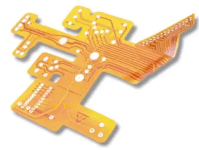
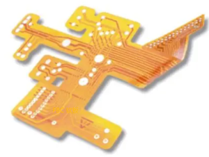
Polyimide (PI) is a high-performance polymer that serves as the primary dielectric substrate for flexible printed circuits and rigid-flex constructions. DuPont Kapton and its equivalents form the foundation of modern flex PCB manufacturing, providing the thermal and mechanical properties required for demanding electronic applications.
Unlike rigid FR-4 substrates, polyimide flexible PCB material enables three-dimensional packaging that rigid boards cannot achieve: folding smartphone displays, wearable health sensors that conform to skin, satellite solar array harnesses that deploy in orbit, and medical implants that flex with body movement. Each application exploits polyimide’s unique ability to maintain electrical reliability under repeated mechanical stress.
Polyimide is the most widely used flexible circuit substrate, accounting for 42.87% of the rigid-flex PCB market in 2025, with a projected CAGR of 6.53% through 2031. The global FPCB market is expected to grow from USD 14.16 billion in 2025 to USD 15.11 billion in 2026, with polyimide consumption tracking closely with FPCB surface-area growth and the transition from rigid to flexible architectures.
For engineers developing next-generation flexible circuits, understanding polyimide material properties is essential for reliable product design. Flex PCB assembly requires careful consideration of substrate material to ensure manufacturing success and long-term reliability.
Key Properties of Polyimide Flexible PCB Material
Polyimide flexible PCB material delivers a distinctive set of electrical, thermal, and mechanical properties that make it the gold standard for flex circuit applications. The following table summarizes representative values from leading material datasheets.
| Property | Typical Value | Test Method | Significance |
|---|---|---|---|
| Dielectric Constant (Dk) @ 1 GHz | 3.2 – 3.5 | IPC-TM-650 2.5.5.3 | Lower than FR-4; suitable for high-speed flex designs |
| Dissipation Factor (Df) @ 1 GHz | 0.002 – 0.008 | IPC-TM-650 2.5.5.3 | Low loss for multi-GHz signaling |
| Temperature Range (Continuous) | -269°C to +400°C | — | Widest range of any organic substrate |
| Glass Transition Temperature (Tg) | >250°C (up to 370°C) | IPC-TM-650 2.4.24.4 | Maintains mechanical integrity through reflow |
| Bend Endurance | 200,000+ cycles | MIT Folding Endurance | Rated for continuous dynamic movement |
| Thickness Range | 25 – 125 μm (1 – 5 mil) | — | From single-film to built-up multilayer flex |
| Tensile Strength @ 23°C | 231 – 375 MPa | ASTM D882 | High mechanical strength for reliable handling |
| Moisture Absorption | 1.5 – 3.0% | IPC-TM-650 2.6.2 | Higher than FR-4 — requires pre-bake before assembly |
| Chemical Resistance | Excellent | — | Resists solvents, acids, and harsh cleaning |
Kapton EN series polyimide films offer enhanced processing capability for fine-feature circuit fabrication, with thickness options from 5.1 μm to 50.8 μm and CTE closely matched to copper for superior dimensional stability. Pyralux AG adhesiveless all-polyimide double-sided copper-clad laminates provide strong dielectric-to-copper bond strength supporting high reliability in demanding applications.
When selecting materials for prototype PCB assembly, engineers should consider the specific thermal and mechanical demands of their application to ensure optimal material choice.
Polyimide vs PET: Critical Material Comparison
While polyester (PET) offers a lower-cost alternative for less demanding applications, polyimide remains the superior choice for high-reliability, solderable flex circuits. Understanding the differences between these materials is essential for making informed design decisions.
| Property | Polyimide (PI) | Polyester (PET) | Implication |
|---|---|---|---|
| Continuous Use Temperature | ~150°C (up to 200°C+ for advanced grades) | 105 – 130°C | PI withstands SMT reflow; PET cannot |
| Flexibility (2mm radius) | Good to Best | Bad | PI supports tighter bend radii |
| Tear Strength | 500g | 800g | PET has higher tear strength but lower overall durability |
| Strip Strength in Air | 1225 – 1750 N/M | 1050 N/M | PI provides better adhesion reliability |
| Cost | 3 – 8× higher than PET | Baseline | PET is cost-effective for less demanding applications |
| Multilayer Capability | Supports multilayer and rigid-flex | Typically single or double layer only | PI enables complex designs |
PET softens and deforms between 130-150°C, making it unsuitable for traditional soldering processes. Polyimide, by contrast, can withstand SMT reflow soldering temperatures and supports complex designs such as multilayer and rigid-flex PCBs. For applications requiring thermal cycling, soldering, or dynamic flexing, polyimide is the mandatory material choice.
For high-volume production runs, high-volume PCB assembly often utilizes polyimide substrates to ensure thermal reliability through repeated reflow cycles.
High-Temperature Performance of Polyimide Flexible PCBs
The thermal performance of polyimide flexible PCB material is one of its most distinguishing characteristics. Advanced polyimide grades can withstand continuous operation up to 200°C and survive repeated lead-free reflow soldering profiles without delamination or degradation.
Blueshift’s PhaseBlue 1500, a next-generation nanoporous polyimide aerogel material, achieves a glass transition temperature of 305°C and decomposition temperature of 530°C — significantly beyond the survivability of PTFE-based systems. With a dielectric constant of 1.3–1.5 at 1 GHz and an ultra-low dissipation factor below 0.001, this material maintains stable dielectric performance across 1–10 GHz without the “dielectric knee” that compromises signal reliability under high temperatures.
Siloxane-containing polyimide films demonstrate glass transition temperatures between 292°C and 420°C, with 5% weight loss temperatures exceeding 500°C. These materials maintain good heat resistance with low dielectric properties and outstanding adhesion, making them suitable for flexible integrated circuit boards, high-frequency electronics, and microelectronics applications.
High-temperature polyimide flex PCBs are essential for automotive under-the-hood sensors, transmission control units, aerospace avionics, industrial thermal monitoring systems, and medical diagnostic equipment requiring sterilization. PCB manufacturing for these demanding applications requires specialized material handling and process controls.
Applications of Polyimide Flexible PCB Material
Polyimide flexible PCB material enables a wide range of applications across multiple industries, leveraging its unique combination of thermal, mechanical, and electrical properties.
Automotive Electronics
Automotive applications demand materials that withstand thermal cycling, vibration, and chemical exposure while maintaining dimensional stability. Polyimide flex PCBs are used in under-hood sensor connections, battery management systems (BMS), compact dashboard displays, ADAS sensor arrays, head-up displays, and EV powertrain control modules. Electric vehicle BMS PCBs often employ rigid-flex construction with polyimide flex layers rated for 500+ bend cycles at -40°C to +200°C.
Aerospace and Defense
Aerospace applications rely on adhesiveless polyimide flex laminates for critical assemblies exposed to thermal shock, sustained high-temperature operation, or vacuum environments. Applications include dynamic-bend flex in gimbals, seeker heads, and UAV flight controls; high-density routing for compact mission electronics; impedance-controlled RF pathways; and spaceflight hardware where outgassing and thermal extremes are critical. Panasonic FELIOS R-F775 flex PCB is NASA outgassing certified (ASTM E-595) for satellite bus architectures and deployable solar arrays.
Consumer Electronics
Polyimide is widely used in smartphones, wearables, tablets, and laptops as flex or rigid-flex PCBs. The material enables foldable phone displays, wearable health sensors, and compact device interconnects. Kapton FPC polyimide film combines MIT folding endurance of up to 285,000 cycles at 25 μm with dimensional stability of 0.03% after thermal exposure.
Medical Devices
Medical applications require materials that can withstand sterilization and heat-intensive operation. Polyimide flex circuits are used in diagnostic equipment, medical implants that flex with body movement, and devices requiring high reliability in challenging environments.
High-Frequency and 5G Communications
Polyimide maintains clean and stable electrical signals even at very high speeds, which is vital for applications such as 5G and radar. However, conventional polyimide’s relatively high dielectric constant (Dk > 3.0 at 10 GHz) has posed challenges for high-frequency flexible circuit boards. New low-dielectric modified polyimide materials with low-temperature curing capability are being developed to address these high-frequency requirements.
For complex designs combining rigid and flexible sections, mixed technology PCB assembly leverages polyimide’s unique properties to create integrated assemblies that eliminate connectors and improve reliability.
Adhesiveless vs Adhesive Polyimide Laminates
Polyimide flexible PCB materials are available in two primary construction types: adhesive-based and adhesiveless laminates. The choice between these options significantly impacts reliability, particularly in high-temperature and dynamic flex applications.
Adhesiveless polyimide flex laminates are manufactured by directly bonding copper to polyimide without an intermediate adhesive layer. By eliminating this layer, adhesiveless constructions provide superior performance in assemblies exposed to thermal shock, sustained high-temperature operation, or vacuum environments. Adhesiveless laminates offer better thermal stability, improved dimensional control, and elimination of outgassing concerns for spaceflight hardware.
Adhesive-based polyimide laminates use acrylic or epoxy bonding layers to join the stackup together. While generally more cost-effective, these constructions may have limitations in extreme thermal environments where adhesive degradation can compromise reliability.
For turnkey PCB assembly, the choice between adhesiveless and adhesive polyimide laminates should be guided by the specific thermal and mechanical requirements of the end application.
Copper Foil Selection for Polyimide Flexible PCBs
Copper foil selection is critical for polyimide flexible PCB performance. Two primary copper types are used:
-
Rolled-Annealed (RA) Copper: Preferred for dynamic bending applications where the circuit will flex repeatedly. RA copper has a grain structure that follows the rolling direction, providing superior fatigue resistance for applications requiring 200,000+ bend cycles.
-
Electrodeposited (ED) Copper: Suitable for static flex or flex-to-install applications where the circuit is bent once during installation and then remains in position. ED copper offers good performance at lower cost for less demanding applications.
DuPont Pyralux AP7163E, an ultra-thin all-polyimide flex laminate, combines rolled-annealed copper with polyimide for applications requiring tight copper-polyimide adhesion through thermal excursions.
Design Guidelines for Polyimide Flexible Circuits
Successful polyimide flexible PCB design requires adherence to specific guidelines that account for the material’s unique properties.
Bend Radius Considerations
The minimum bend radius for polyimide flexible circuits depends on layer count and copper type. For single-layer constructions, bend radii of 6–10× material thickness are typical, while advanced adhesiveless materials can achieve 3–6× thickness. Dynamic flex applications require larger bend radii to ensure long-term reliability.
Thermal Management
Polyimide’s moisture absorption of 1.5–3.0% requires pre-baking before assembly to prevent blistering during reflow. The material’s coefficient of thermal expansion should be considered in multilayer designs to prevent stress-related failures.
Dimensional Stability
Kapton FPC polyimide film offers dimensional stability of 0.03% after thermal exposure, essential for maintaining registration in fine-pitch circuitry. Controlled expansion with proper film handling ensures reliable manufacturing outcomes.
Frequently Asked Questions About Polyimide Flexible PCB Material
What is the maximum temperature for polyimide flexible PCBs?
Polyimide flexible PCBs can operate continuously from -269°C to +400°C, with advanced grades rated for continuous operation up to 200°C and capable of surviving lead-free reflow soldering profiles without degradation.
How does polyimide compare to FR-4 for PCB applications?
Polyimide offers superior thermal resistance, mechanical flexibility, and lower dielectric constant than FR-4, making it the preferred choice for flex and rigid-flex applications. FR-4 remains the standard for rigid PCBs where flexibility is not required.
Can polyimide flexible PCBs be used for high-frequency applications?
Yes, polyimide is used in high-frequency applications including 5G and radar. However, conventional polyimide has a dielectric constant above 3.0 at 10 GHz, which has prompted development of low-dielectric modified polyimide materials for next-generation high-frequency flex circuits.
What is the difference between Kapton and polyimide?
Kapton is DuPont’s brand name for polyimide film. Polyimide is the generic material class, while Kapton represents specific commercially available grades that have become the industry standard for flexible circuit substrates.
How many bend cycles can polyimide flexible PCBs withstand?
Polyimide flexible PCBs can withstand 200,000+ bend cycles for dynamic flex applications. Kapton FPC polyimide film achieves MIT folding endurance of up to 285,000 cycles at 25 μm thickness.
Key Takeaways
-
Polyimide is the industry-standard substrate for flexible printed circuits, offering unmatched thermal endurance (-269°C to +400°C), mechanical flexibility (200,000+ bend cycles), and chemical resistance.
-
Performance advantages over PET include the ability to withstand SMT reflow soldering, support for multilayer and rigid-flex designs, and superior thermal and mechanical reliability.
-
Adhesiveless constructions provide superior performance in thermal shock, high-temperature operation, and vacuum environments, making them preferred for aerospace and spaceflight applications.
-
Material selection should consider thermal requirements, bend cycle expectations, cost constraints, and manufacturing process compatibility.
-
Market growth reflects increasing demand: polyimide holds 42.87% of the rigid-flex PCB market with 6.53% CAGR projected through 2031.
Get Expert Support for Your Polyimide Flexible PCB Project
Selecting the right polyimide flexible PCB material and ensuring reliable manufacturing requires technical expertise and experience. Whether you’re developing a prototype, scaling to high-volume production, or designing a complex rigid-flex assembly, our engineering team can provide the guidance you need.
Contact us for a free DFM analysis and technical consultation on your polyimide flexible PCB project. Upload your design files and receive professional feedback on material selection, stackup optimization, and manufacturability improvements.