Aluminum vs FR4 PCB Material: Thermal Conductivity, Cost, and Selection Guide
Aluminum PCBs deliver thermal conductivity 4–10× higher than FR4 through a metal core that acts as a built-in heatsink, while FR4 remains the industry-standard electrical insulator for multi-layer digital designs. FR4 offers superior electrical insulation, lower cost, and supports complex routing; aluminum excels in thermal management for high-power LEDs, power electronics, and automotive lighting where junction temperature directly determines product lifespan. The choice ultimately depends on power density: below 1 W/cm², FR4 is usually sufficient and more economical; above 2 W/cm², aluminum MCPCB becomes the thermally reliable solution.
What Is the Difference Between Aluminum PCB and FR4?
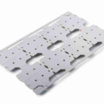
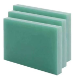
Aluminum PCBs—also called Metal Core PCBs (MCPCBs)—replace the fiberglass substrate with an aluminum alloy base plate sandwiched with a thermally conductive but electrically insulating dielectric layer. FR4 (Flame Retardant 4) is a glass-reinforced epoxy laminate that accounts for over 90% of all PCBs manufactured worldwide.
The fundamental distinction is thermal: FR4 is an electrical insulator and structural material with poor heat conduction, while aluminum is a thermal conductor that actively spreads and dissipates heat.
Thermal Conductivity Comparison: Aluminum vs FR4
The thermal performance gap between these materials is substantial. FR4’s through-thickness thermal conductivity typically ranges from 0.25 to 0.4 W/m·K, making it effectively a thermal insulator. Aluminum PCBs achieve 1.0 to 4.0 W/m·K through the dielectric layer, with the aluminum base itself conducting at 150–220 W/m·K—over 400× better than FR-4.
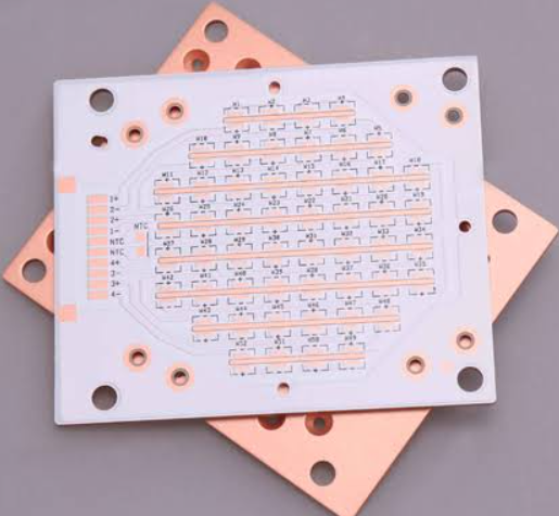
In practical terms, aluminum PCBs reduce LED junction temperatures by 20–40°C compared to FR-4 at the same power dissipation. A 3W LED on standard FR-4 without thermal relief can experience a 210°C temperature rise from board bottom to junction—catastrophic for reliability.
| Property | FR4 (Standard) | Aluminum PCB (MCPCB) | Unit |
|---|---|---|---|
| Board thermal conductivity (through-thickness) | 0.25–0.4 | 1.0–4.0 (dielectric) / 150–220 (base) | W/m·K |
| Typical thermal resistance (per cm²) | ~40–70 | 0.5–2.5 | °C/W |
| Junction temperature reduction vs bare FR4 | Baseline | 20–40 | °C |
| LED lifespan impact | ~25,000 hrs | 50,000+ hrs | hours |
The critical engineering parameter is the dielectric layer—typically 75–200 µm thick with ceramic fillers (alumina or boron nitride) dispersed in epoxy. At 75 µm thickness with 2.0 W/m·K thermal conductivity, thermal resistance is just 0.375 °C·cm²/W; at 150 µm with 1.0 W/m·K, it jumps to 1.5 °C·cm²/W—a 4× difference from dielectric specification alone.
Structure and Construction
FR4 construction is straightforward: woven fiberglass cloth impregnated with epoxy resin, with copper foil laminated on one or both sides. Layer counts range from 1 to 30+, supporting complex multi-layer routing.
Aluminum MCPCBs have a three-layer sandwich structure:
- Copper circuit layer: 35–140 µm (1–4 oz) for trace routing
- Thermally conductive dielectric: 75–200 µm, 1.0–5.0+ W/m·K, providing electrical isolation (3–6 kV breakdown)
- Aluminum base plate: 0.8–3.2 mm, typically 5052 or 6061 alloy, acting as the heat spreader
Unlike FR4, aluminum PCBs are typically single-sided (occasionally double-sided) because the metal core prevents plated through-holes and limits routing layers.
Cost Comparison: Aluminum vs FR4
FR4 is the most cost-effective PCB material due to mature manufacturing processes and abundant raw material supply. Aluminum PCBs carry a significant premium—typically 1.2× to 3× the cost of equivalent FR4 boards.
This cost difference stems from:
- Higher raw material cost of aluminum vs fiberglass
- Specialized milling and surface treatment requirements
- More expensive high-thermal-conductivity dielectric layers
- Longer lead times (7–10 days vs 3–5 for FR4)
However, system-level cost may favor aluminum when external heatsinks can be eliminated—the board itself becomes the heatsink. For high-power LED arrays, eliminating a separate heatsink can offset the higher substrate cost.
Electrical Properties: Dielectric Constant and Insulation
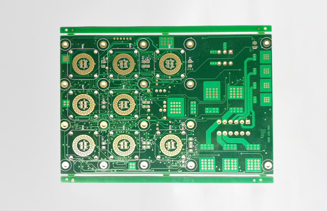
FR4 offers superior and stable dielectric properties with Dk of 4.2–4.8 at 1 MHz and dissipation factor of 0.015–0.025. This makes it suitable for high-speed digital and RF applications up to 1–2 GHz.
Aluminum PCBs have a dielectric constant around 4.0 and rely on the dielectric layer for electrical isolation. Breakdown voltage typically exceeds 3 kV (standard) and can reach 5 kV for enhanced grades. However, aluminum’s lower Dk stability and the single-layer routing constraint make it unsuitable for complex digital or high-frequency designs.
CTE and Reliability Under Thermal Cycling
Coefficient of Thermal Expansion (CTE) mismatch is a critical reliability consideration. FR4 has a Z-axis CTE of 40–70 ppm/°C (below Tg). Aluminum expands at ~23 ppm/°C. Copper traces expand at ~17 ppm/°C.
FR4 faces via barrel cracking from CTE mismatch between copper (17 ppm/°C) and FR4 Z-axis (50–70 ppm/°C) during thermal cycling. Aluminum PCBs face dielectric shear stress from Al-Cu CTE mismatch (23 vs 17 ppm/°C).
Interestingly, aluminum substrates can withstand over 2000 thermal cycles (0°C to 100°C) without failure, while FR4 typically fails around 150 cycles. However, solder joints on aluminum substrates exhibit greater degradation under thermal cycling due to the stiff metal base transferring more stress to solder connections.
Manufacturing Considerations
FR4 fabrication is universally supported with standard drill, plating, and lamination processes. It supports plated through-holes, multi-layer routing, and complex outlines.
Aluminum PCB manufacturing requires specialized processes:
- Drill speeds and feed rates must be optimized for aluminum—standard FR4 parameters cause excessive tool wear
- Aluminum cannot survive the thermal stress of plated through-hole fabrication without compromising reliability
- Simple rectangular shapes are preferred over complex outlines
- Single-sided designs are most cost-effective and reliable
Dielectric Layer Grades for Aluminum PCBs
The dielectric layer is the most critical component of an MCPCB—it must be electrically insulating while being as thermally conductive as possible. Thermal conductivity grades typically range from 1.0 to 8.0+ W/m·K.
| Grade | Thermal Conductivity | Typical Thickness | Applications |
|---|---|---|---|
| Standard | 1.0–1.5 W/m·K | 75–100 µm | General LED lighting, cost-sensitive designs |
| Enhanced | 2.0–3.0 W/m·K | 75–100 µm | High-power LED, automotive lighting |
| Premium | 3.0–5.0+ W/m·K | 50–75 µm | Extreme power, COB LED, motor drives |
Key tradeoff: Higher thermal conductivity dielectrics cost more and may have lower breakdown voltage. For mid-range automotive auxiliary lights, 2.0 W/m·K dielectric is often the “sweet spot”.
Application Scenarios: When to Choose Which
Choose FR4 when:
- Power density is below 1 W/cm²
- Design requires 4+ signal layers or complex routing
- Application is cost-sensitive consumer electronics
- Operating frequencies exceed 1–2 GHz (RF/microwave)
- Board requires complex mechanical outlines
Choose aluminum MCPCB when:
- Power density exceeds 2 W/cm²
- Design uses high-power LEDs, MOSFETs, or voltage regulators
- No external heatsink is available—the board is the heatsink
- Single-sided or double-sided design with 1–2 routing layers
- Operating voltage below 500V (dielectric limit)
- High-volume production of a single-function board
Rule of thumb: If your design is single-sided and power density exceeds 1 W/cm², aluminum wins on thermals, reliability, and total system cost. If you need inner signal layers, stick with FR4 and design a proper thermal via array.
Thermal Vias as a FR4 Workaround
Engineers have developed workarounds to improve FR4 thermal performance—thermal vias, copper pours, and exposed copper pads with thermal interface material to external heatsinks. Thermal via arrays (0.3 mm vias on 0.6 mm pitch) can reduce effective thermal resistance by 60–70%.
FR4 with thermal vias achieves board thermal conductivity of 2–8 W/m·K (via array), approaching aluminum’s dielectric performance. However, this approach adds complexity, assembly steps, and cost—typically 1.2–1.5× baseline FR4 cost.
For high-output industrial LEDs, thermal vias are often insufficient and significantly increase fabrication complexity and cost.
Common Questions About Aluminum vs FR4 PCB Material
Is aluminum PCB better than FR4?
Aluminum is better for thermal management in high-power applications—delivering 4–10× higher thermal conductivity and 20–40°C lower junction temperatures. FR4 is better for electrical performance, multi-layer routing, and cost-sensitive designs. Neither is universally “better”—the choice depends on your application’s power density, layer count, and cost constraints.
Can FR4 be used for LED lighting?
FR4 can be used for low-power indicator LEDs (below 1 W/cm²). For high-power LED arrays (streetlights, automotive, grow lights), aluminum MCPCB is strongly recommended to prevent junction temperature rise, brightness reduction, color shift, and premature failure.
Why is aluminum PCB more expensive than FR4?
Aluminum PCBs cost 1.2× to 3× more due to higher raw material costs, specialized manufacturing processes (milling, surface treatment), expensive high-thermal-conductivity dielectrics, and longer lead times.
What is the thermal conductivity of FR4 vs aluminum?
FR4: 0.25–0.4 W/m·K (through-thickness). Aluminum PCB dielectric: 1.0–5.0+ W/m·K; aluminum base: 150–220 W/m·K.
Does aluminum PCB require special manufacturing?
Yes. Aluminum requires optimized drill parameters to prevent tool wear, cannot support plated through-holes reliably, and prefers simple rectangular shapes.
Key Takeaways
- Thermal conductivity: Aluminum (1.0–4.0 W/m·K dielectric, 150–220 W/m·K base) vs FR4 (0.25–0.4 W/m·K)—a 4–10× improvement through the dielectric alone
- Cost: Aluminum PCBs are 1.2–3× more expensive than equivalent FR4
- Layer count: FR4 supports 1–30+ layers; aluminum is typically single-sided (occasionally double-sided)
- Electrical insulation: FR4 offers superior, stable Dk (4.2–4.8) for high-speed digital; aluminum relies on a dielectric layer with ~4.0 Dk
- Reliability: Aluminum withstands more thermal cycles (>2000 vs ~150 for FR4) but places greater stress on solder joints under cycling
- Decision rule: Below 1 W/cm² → FR4. Above 2 W/cm² with single-sided design → aluminum MCPCB
Choosing the right PCB material is one of the most impactful decisions in board design. If your project demands superior thermal management for high-power applications, explore our PCB manufacturing capabilities or consult our design layout team for material selection guidance. For complex multi-layer designs requiring FR4, our prototype PCB assembly services support rapid iteration. If you’re developing power electronics, our SMT PCB assembly and turnkey PCB assembly solutions can help optimize your thermal management strategy from prototype to production.
Need help determining the right material for your specific application? Contact our engineering team for a free thermal analysis and DFM review—upload your design files and get expert recommendations on aluminum vs FR4 selection within 24 hours.
Sources
- AtlasPCB. “Aluminum PCB vs FR-4 for Thermal Management: Which Base Material Wins for LED and Power Designs?” AtlasPCB Engineering, 2026.
- Beauchamp, Jeffrey. “Metal-Core PCBs and Thermal Management.” Printed Circuit Design & Fab Online Magazine, 2 Jan. 2026.
- JLCPCB. “Aluminum PCBs vs. Traditional FR4: A Comparative Analysis of Thermal Management.” JLCPCB Blog, updated 24 Jan. 2026.
- PCBONLINE. “A Comparison of Rigid Circuit Boards: FR4, Metal, PTFE, Ceramic.” PCBONLINE Blog, 14 Nov. 2025.
- IPCB. “A Comparison of FR-4, Aluminium Substrates and Flexible Printed Circuit Boards.” IPCB, 2026.
- AtlasPCB. “PCB Materials Guide.” AtlasPCB Engineering, 2026.