Aluminum PCB Dielectric Material: Complete Guide to Properties, Selection & Thermal Performance
An aluminum PCB dielectric material is the thermally conductive but electrically insulating layer sandwiched between the copper circuit and the aluminum base plate. It enables heat dissipation from power components while preventing electrical shorts. For high-power LED arrays and motor drivers, select a dielectric with thermal conductivity of at least 2.0 W/m·K and dielectric thickness between 75–150 μm to balance heat transfer with breakdown voltage requirements.
What Is an Aluminum PCB Dielectric Material?
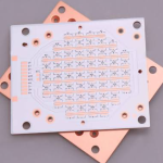
An aluminum PCB—also called a metal core PCB (MCPCB) or insulated metal substrate (IMS)—uses an aluminum alloy base plate as an integrated heat spreader. The dielectric layer is the critical middle layer that bonds the copper circuit to the aluminum base while providing electrical isolation and a thermal conduction path.
Unlike standard FR-4, which has a bulk thermal conductivity of approximately 0.25 W/m·K, aluminum PCB dielectric materials are engineered with ceramic fillers such as aluminum oxide (Al₂O₃), aluminum nitride (AlN), or boron nitride (BN) to achieve thermal conductivity values from 1.0 to over 5.0 W/m·K. This dramatic improvement in thermal performance is what makes aluminum PCBs the preferred choice for applications requiring efficient heat dissipation, such as LED lighting, automotive power electronics, and motor drives.
The dielectric layer typically ranges from 50 to 200 μm in thickness. Thinner dielectrics reduce thermal resistance but lower breakdown voltage, while thicker dielectrics provide better electrical insulation at the cost of thermal performance.
At gopcb, we specialize in manufacturing aluminum PCBs with precisely engineered dielectric layers tailored to your application’s thermal and electrical requirements.
Why the Dielectric Layer Is the Critical Bottleneck
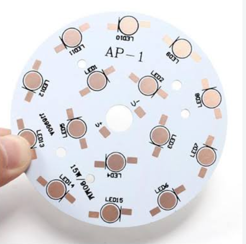
The dielectric layer is where aluminum PCB performance is actually determined—it must do two contradictory things simultaneously: provide electrical insulation between the copper traces and the aluminum base, while conducting heat as efficiently as possible downward into the metal.
Standard FR4 dielectric manages only 0.25 W/m·K. Modern ceramic-filled polymer dielectrics used in quality MCPCB laminates achieve 1.0–10 W/m·K. The ceramic fillers—typically aluminum oxide (Al₂O₃), aluminum nitride (AlN), or boron nitride (BN)—raise thermal conductivity dramatically while maintaining electrical breakdown strength.
The thermal resistance of the dielectric layer can be calculated as:
Thermal Resistance (°C·cm²/W) = Dielectric Thickness (cm) / Thermal Conductivity (W/m·K)
At 75 μm thickness with 2.0 W/m·K thermal conductivity, the per-unit-area thermal resistance is approximately 0.375 °C·cm²/W. At 150 μm with 1.0 W/m·K, thermal resistance jumps to 1.5 °C·cm²/W—four times higher.
Key Dielectric Material Properties for Aluminum PCBs
Thermal Conductivity
Thermal conductivity is the most critical parameter for aluminum PCB dielectric materials. It determines how efficiently heat transfers from the copper circuit layer through the dielectric to the aluminum base.
Typical dielectric materials have thermal conductivities between 0.8 to 1.5 W/m·K. However, high-quality materials with conductivities of 2.0–3.0 W/m·K are more desirable for high-power applications such as LED lights or motor drivers. Premium ceramic-filled dielectrics can exceed 6.0 W/m·K.
| Dielectric Grade | Thermal Conductivity (W/m·K) | Typical Thickness (μm) | Typical Application |
|---|---|---|---|
| Standard Epoxy | 0.8–1.5 | 100–200 | General-purpose LED lighting |
| High-Performance Ceramic-Filled | 2.0–3.0 | 75–150 | High-power LEDs, motor drivers |
| Premium (e.g., Bergquist Thermal Clad) | 3.0–4.1 | 38–100 | Automotive, high-reliability power |
| Ultra-High Performance | 5.0–10.0+ | 50–75 | Specialized high-power, RF power |
Dielectric Constant
The dielectric constant (Dk) measures a material’s ability to store electrical energy in an electric field. For aluminum PCBs, Dk typically ranges from 3.5 to 4.5, which is lower than FR-4’s 4.2–4.6 range.
A lower dielectric constant enables tighter trace spacing without signal integrity compromise and is particularly important for high-frequency and RF applications. For designs requiring minimal signal delay and crosstalk, materials with Dk values around 3.5 are preferred.
Dielectric Breakdown Voltage
Breakdown voltage is the maximum voltage the dielectric layer can withstand before electrical current punches through it. This is a critical safety parameter, especially in high-voltage systems like power supplies and automotive electronics.
Standard aluminum PCB dielectrics typically provide breakdown voltages of 2–3 kV, while premium materials can exceed 4 kV/mm. Thinner dielectrics reduce thermal resistance but also lower breakdown voltage—engineers must balance these competing requirements based on application needs.
Dielectric Loss Tangent
The dielectric loss tangent (dissipation factor) indicates how much energy is lost as heat within the dielectric material when subjected to an alternating electric field. Lower values are preferred for high-frequency applications. Typical aluminum PCB dielectrics have loss tangents around 0.02–0.03 at 1 MHz.
Common Aluminum PCB Dielectric Material Types
Epoxy-Based Dielectrics
Epoxy-based dielectrics are the most common matrix material, offering good adhesion, manufacturing reliability, and cost-effectiveness. When filled with 50–70% ceramic particles, they achieve thermal conductivity in the 1.0–3.0 W/m·K range.
Standard epoxy dielectrics are suitable for general-purpose LED lighting and consumer electronics where cost is a primary consideration.
Polyimide-Based Dielectrics
Polyimide-based dielectrics offer superior thermal stability and reliability, making them ideal for applications with wide temperature ranges (-40 to +125°C) such as automotive electronics, or critical reliability requirements like medical and aerospace devices. Polyimide dielectrics are also used in flexible and rigid-flex PCB applications.
Ceramic-Filled Polymer Dielectrics
These are the highest-performing dielectrics, using ceramic fillers such as aluminum oxide (Al₂O₃), aluminum nitride (AlN), or boron nitride (BN) within a polymer matrix. They achieve thermal conductivity from 2.0 to over 10.0 W/m·K while maintaining excellent electrical insulation properties.
Bergquist Thermal Clad dielectrics, widely used in automotive and high-reliability applications, deliver 2.4 to 4.1 W/m·K.
Specialty Dielectrics for High-Frequency Applications
For RF and microwave applications, specialty dielectrics such as PTFE-based or low-loss polyimide materials are available. These offer controlled dielectric constants in the 3.5–4.5 range with minimal dissipation at microwave frequencies.
Aluminum PCB Dielectric vs. FR-4: A Thermal Comparison
The fundamental difference between aluminum PCB dielectrics and FR-4 is thermal conductivity. FR-4’s bulk thermal conductivity is approximately 0.25 W/m·K, while aluminum PCB dielectrics range from 1.0 to 5.0+ W/m·K—a 4× to 20× improvement.
In practical terms, this means aluminum PCBs reduce LED junction temperatures by 20–40°C compared to FR-4 at the same power dissipation. The aluminum base itself provides thermal conductivity of 150–220 W/m·K—over 400× better than FR-4—enabling efficient heat transfer from components to heatsinks or enclosures.
For designs with power density exceeding 1 W/cm², aluminum PCBs win on thermals, reliability, and total system cost.
If you’re evaluating whether an aluminum PCB is right for your project, explore our PCB manufacturing capabilities to see how we can support your thermal management needs.
How to Select the Right Dielectric Material for Your Aluminum PCB
Step 1: Define Your Thermal Requirements
Calculate the power dissipation of your components and the maximum allowable junction temperature. For LED arrays dissipating >2W per device, select a dielectric with ≥2.0 W/m·K. For motor drivers handling 10–50A continuous current, use ≥3.0 W/m·K dielectric.
Step 2: Determine Voltage Requirements
Identify the maximum operating voltage of your system. For low-voltage (12–48V) LED applications, standard 2–3 kV breakdown voltage is typically sufficient. For automotive or industrial power supplies with higher voltages, specify dielectrics with ≥4 kV breakdown voltage.
Step 3: Consider Signal Integrity Needs
For high-frequency or RF applications, prioritize dielectrics with low dielectric constant (around 3.5) and low loss tangent to minimize signal delay and crosstalk.
Step 4: Evaluate Environmental Conditions
Consider the operating temperature range, humidity, and chemical exposure. Polyimide-based dielectrics offer superior performance in extreme environments, while standard epoxy dielectrics are suitable for controlled indoor environments.
Step 5: Balance Cost vs. Performance
Higher thermal conductivity dielectrics cost more but can reduce or eliminate the need for external heatsinks, potentially lowering overall system cost.
Dielectric Material Selection Checklist
- Thermal conductivity: ≥1.0 W/m·K for general use, ≥2.0 W/m·K for high-power, ≥3.0 W/m·K for extreme power density
- Dielectric thickness: 75–150 μm for most applications; thinner (38–75 μm) for maximum heat transfer
- Breakdown voltage: ≥2 kV for low-voltage, ≥4 kV for automotive/industrial
- Dielectric constant: 3.5–4.5 for general use; lower for RF/high-frequency
- Operating temperature range: Match to your application’s thermal environment
- IPC compliance: IPC-4101 or IPC-4103 for rigid and high-frequency materials
Our PCB design and layout team can help you select the optimal dielectric material for your specific application requirements.
Common Applications and Dielectric Recommendations
| Application | Recommended Thermal Conductivity | Recommended Thickness | Key Consideration |
|---|---|---|---|
| Standard LED lighting | 1.0–2.0 W/m·K | 100–150 μm | Cost-effectiveness |
| High-power LED arrays | 2.0–3.0 W/m·K | 75–100 μm | Junction temperature reduction |
| Automotive headlight drivers | 3.0–4.1 W/m·K | 50–100 μm | Reliability, 15-year service life |
| Motor drives & power converters | 2.0–3.0 W/m·K | 75–150 μm | High current handling |
| RF/microwave power amplifiers | 1.0–2.0 W/m·K | 100–200 μm | Low Dk, low loss tangent |
| EV battery management systems | 3.0–4.0+ W/m·K | 50–100 μm | High voltage isolation |
For complex designs requiring both thermal management and multi-layer routing, explore our mixed technology PCB assembly services.
Frequently Asked Questions About Aluminum PCB Dielectric Materials
What is the thermal conductivity of standard aluminum PCB dielectric?
Standard aluminum PCB dielectric materials have thermal conductivity ranging from 0.8 to 1.5 W/m·K. High-performance ceramic-filled dielectrics achieve 2.0–3.0 W/m·K, and premium materials can exceed 5.0 W/m·K.
How does dielectric thickness affect performance?
Thinner dielectrics (50–75 μm) reduce thermal resistance for better heat transfer but lower breakdown voltage. Thicker dielectrics (150–200 μm) provide better electrical insulation but higher thermal resistance. Most applications balance these with 75–150 μm thickness.
What is the dielectric constant of aluminum PCB materials?
Aluminum PCB dielectrics typically have a dielectric constant of 3.5–4.5, which is lower than FR-4’s 4.2–4.6 range. This enables tighter trace spacing and better signal integrity.
What breakdown voltage can aluminum PCB dielectrics withstand?
Standard aluminum PCB dielectrics provide 2–3 kV breakdown voltage. Premium materials can exceed 4 kV/mm, making them suitable for automotive and high-voltage industrial applications.
What materials are used in aluminum PCB dielectrics?
Common dielectric materials include epoxy resin, polyimide, and ceramic-filled polymers with aluminum oxide (Al₂O₃), aluminum nitride (AlN), or boron nitride (BN) fillers.
How do aluminum PCBs compare to FR-4 for thermal management?
Aluminum PCBs reduce junction temperatures by 20–40°C compared to FR-4 at the same power dissipation, thanks to their dielectric layer (1.0–3.0 W/m·K) and aluminum base (150–220 W/m·K) versus FR-4’s 0.25 W/m·K.
Key Takeaways
- The dielectric layer is the critical performance bottleneck in aluminum PCBs—it must provide electrical insulation while conducting heat efficiently.
- Thermal conductivity ranges from 0.8 W/m·K (standard) to 5.0+ W/m·K (premium ceramic-filled). Select ≥2.0 W/m·K for high-power applications.
- Dielectric thickness typically ranges from 50–200 μm; thinner = better heat transfer, thicker = better voltage isolation.
- Dielectric constant (3.5–4.5) is lower than FR-4 (4.2–4.6), enabling better signal integrity for high-frequency designs.
- Breakdown voltage of 2–3 kV is standard; premium materials exceed 4 kV/mm for automotive and industrial applications.
- Common dielectric materials: epoxy-based (cost-effective), polyimide-based (high reliability), ceramic-filled (highest performance).
- Aluminum PCBs reduce junction temperatures by 20–40°C compared to FR-4—critical for LED and power electronics reliability.
Need expert guidance on selecting the right dielectric material for your aluminum PCB? Our engineering team provides free technical consultation to help you optimize thermal performance, reliability, and cost for your specific application.
Explore our full range of prototype PCB assembly, low-volume PCB assembly, and high-volume PCB assembly services—all backed by rigorous material selection and quality control.