FR4 Fiberglass PCB Material: Complete Technical Specifications and Selection Guide (2026)
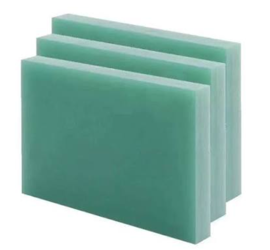
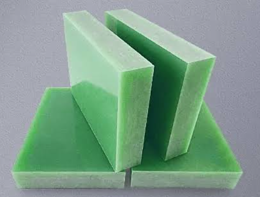
FR4 fiberglass PCB material is a glass-reinforced epoxy laminate that serves as the industry-standard base material for rigid printed circuit boards. It offers an optimal balance of electrical insulation, mechanical strength, thermal stability, and cost-effectiveness for the majority of PCB applications. Standard FR4 typically provides a dielectric constant (Dk) of 4.2–4.7, a dissipation factor (Df) of 0.015–0.020, and a glass transition temperature (Tg) of 130–140°C.
What Is FR4 Fiberglass PCB Material?
FR4 is a thermoset composite material classified within the copper-clad laminate (CCL) family. The “FR” stands for “flame-retardant,” indicating compliance with UL94 V-0 flammability standards. The “4” designates woven glass fabric reinforcement with an epoxy resin binder.
FR4 fiberglass PCB material is composed of three primary components:
- Epoxy Resin: The primary binding agent, typically bisphenol-A epoxy with brominated variants for enhanced flame retardancy. Provides adhesion between layers, electrical insulation, and chemical resistance.
- Glass Fiber Reinforcement: E-glass (alumino-borosilicate glass) woven into fabrics of varying thicknesses (e.g., 1080, 2116, 7628 weaves). Provides mechanical rigidity, dimensional stability, and resistance to warpage.
- Copper Foil: Bonded to one or both surfaces, serving as the conductive layer. Copper thickness ranges from 0.5 oz (17.5 μm) for fine-pitch designs to 4 oz (140 μm) or more for high-current applications.
The glass fiber weave typically accounts for 30% to 50% of the laminate’s weight, imparting mechanical strength and stabilizing dimensional characteristics. This composite structure is what gives FR4 fiberglass PCB material its unique combination of properties that make it suitable for such a wide range of applications.
Key Technical Specifications of FR4 Fiberglass PCB Material
Understanding the technical specifications of FR4 fiberglass PCB material is essential for proper material selection. The table below compares standard FR4 with high-Tg FR4 across all critical parameters.
| Property | Standard FR4 | High-Tg FR4 (Tg 170–180°C) | Test Method |
|---|---|---|---|
| Glass Transition Temperature (Tg) | 130–140°C | 170–180°C | DSC |
| Dielectric Constant (Dk @ 1GHz) | 4.2–4.7 | 4.3–4.6 | IPC-TM-650 |
| Dissipation Factor (Df) | 0.015–0.020 | 0.010–0.015 | IPC-TM-650 |
| Thermal Conductivity | 0.25–0.35 W/m·K | 0.35–0.45 W/m·K | Laser Flash |
| CTE (Z-axis) | 3.5%–4.5% | 2.2%–2.8% | TMA |
| Flammability | V-0 | V-0 | UL94 |
Recent experimental research published in the Journal of Materials Research and Technology (2026) provides high-fidelity thermal characterization data for FR4 laminates. The study reports coefficients of thermal expansion of 31.9 × 10⁻⁶ K⁻¹ in the X direction, 31.7 × 10⁻⁶ K⁻¹ in the Y direction, and 35.8 × 10⁻⁶ K⁻¹ in the Z direction (through thickness). Thermal conductivity values range between 3.4 and 4.5 W·m⁻¹·K⁻¹ in-plane and between 0.35 and 0.38 W·m⁻¹·K⁻¹ through-thickness. This high-fidelity dataset provides critical input for improving thermomechanical reliability simulations in high-density electronic packaging.
Electrical Properties: Dielectric Constant and Dissipation Factor
The electrical performance of FR4 fiberglass PCB material is defined by two key parameters: dielectric constant (Dk) and dissipation factor (Df).
Dielectric Constant (Dk)
The dielectric constant of FR4 fiberglass PCB material controls signal velocity and characteristic impedance. Standard FR4 typically exhibits a Dk of approximately 4.2 to 4.7. However, Dk is not a constant value—one real FR4 datasheet reports 4.46 at 100 MHz and 4.32 at 5 GHz on the same laminate. This frequency-dependent variation must be considered in high-speed designs.
The woven glass structure of FR4 fiberglass PCB material creates localized Dk variation depending on whether a trace sits over a glass bundle or a resin pocket—a phenomenon called “fiber weave effect” that becomes significant at fine trace widths below 5 mil. Glass bundles have a Dk near 6, while resin pockets are near 3.0 to 3.5, driving fiber weave skew of roughly 5 to 15 ps per inch on common weaves.
Dissipation Factor (Df)
The dissipation factor, also called loss tangent (tan δ), quantifies how much electromagnetic energy the material converts to heat as signals pass through it. FR4 fiberglass PCB material has a Df of approximately 0.015–0.025. Dielectric loss scales linearly with frequency—double the frequency, double the dB/inch loss from the dielectric alone.
For designs operating at data rates below 5 Gbps, standard FR4 (Dk ~4.2–4.5, Df ~0.020) often suffices. Above 10 Gbps, low-loss laminates become necessary.
Thermal Properties: Tg, Td, and CTE
The thermal performance of FR4 fiberglass PCB material is critical for reliability, particularly with lead-free assembly processes that expose boards to higher temperatures.
Glass Transition Temperature (Tg)
The glass transition temperature is the temperature at which the resin system transitions from a rigid, glassy state to a rubbery, elastic state. Standard FR4 fiberglass PCB material has a Tg of 130–140°C, while high-Tg FR4 offers 170–180°C. Above Tg, the coefficient of thermal expansion increases significantly—FR4’s Z-axis CTE jumps from 45–70 ppm/°C below Tg to 190–300 ppm/°C above it.
Decomposition Temperature (Td)
The decomposition temperature indicates the temperature at which the material begins to break down irreversibly. Standard FR4 fiberglass PCB material has a Td of 310–350°C at 5% weight loss. For reliable lead-free assembly, specify materials with Tg ≥ 170°C and Td ≥ 340°C.
Coefficient of Thermal Expansion (CTE)
CTE mismatch between copper (17 ppm/°C) and FR4 resin (50–70 ppm/°C in Z-axis) generates cumulative stress during thermal cycling. For the X/Y plane, a CTE value between 11 and 18 ppm/°C is typical for FR4 class materials and generally compatible with copper conductors. For the Z-axis, target below 70 ppm/°C for standard designs and below 55 ppm/°C for high-reliability applications.
Thermal Conductivity of FR4 Fiberglass PCB Material
The thermal conductivity of FR4 fiberglass PCB material is anisotropic—it differs between in-plane and through-thickness directions. Through-thickness thermal conductivity ranges from 0.25 to 0.35 W/m·K for standard FR4 and 0.35 to 0.45 W/m·K for high-Tg FR4. In-plane thermal conductivity is significantly higher, ranging from 0.81 to 1.059 W/m·K. This anisotropy means heat spreads more easily across the board surface than through its thickness, which has important implications for thermal management in high-power designs.
For perspective, copper has a thermal conductivity of approximately 400 W/m·K, while typical FR4 is about 0.2 W/m·K. This large disparity means that copper planes and vias are critical for conducting heat away from components mounted on FR4 boards.
FR4 Fiberglass PCB Material Grades and IPC-4101 Classification
FR4 is a flammability grade, not a material specification. Two boards can both be honestly quoted as FR4 and behave completely differently in a lead-free oven. The document that carries specific requirements is IPC-4101, the base material specification for rigid and multilayer boards.
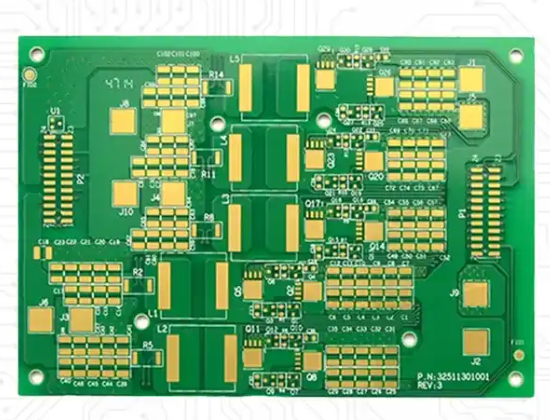
IPC-4101 uses specification sheets, called “slash sheets,” that each define minimum performance for a class of laminate. Key slash sheets for FR4 fiberglass PCB material include:
- IPC-4101/21 and /121: Standard FR4 epoxy, Tg minimum ~110°C—consumer and low-stress designs
- IPC-4101/24 and /124: Mid-Tg epoxy, roughly 150°C class—general lead-free work
- IPC-4101/126 (filled) and /129 (unfilled): High-performance epoxy for lead-free, Tg ≥ 170°C with Td ≥ 340°C—multilayer, automotive, server applications
- IPC-4101/92, /93, /99, /101, /129: Non-halogenated systems—halogen-free product requirements
Writing “FR4” alone on a drawing lets the fabricator pick anything in the family. Always specify the appropriate IPC-4101 slash sheet number to ensure consistent material properties.
Moisture Absorption and Environmental Considerations
FR4 fiberglass PCB material absorbs moisture from the environment, which affects its electrical and mechanical properties. At 30°C and 60% RH, a standard 1.6 mm FR4 board reaches 50% saturation in approximately 48–72 hours and near-full saturation in 2–4 weeks.
Standard FR4 has a 24-hour moisture absorption of 0.10–0.15% and equilibrium absorption of 0.35–0.50%. High-Tg FR4 offers improved moisture resistance with 0.08–0.12% 24-hour absorption. Moisture absorption increases Dk and Df, reduces insulation resistance, and can cause delamination during soldering.
Standard vs. High-Tg FR4: When to Upgrade
Standard FR4 fiberglass PCB material (Tg 130–140°C) is adequate for most designs with peak board temperatures under 130°C. Upgrade to high-Tg FR4 (Tg 170°C+) when:
- Reflow cycles exceed two passes
- Ambient operating temperatures stay above 130°C
- Boards have more than 6 layers
- Automotive, industrial, or high-reliability applications require IPC Class 3 compliance
- Board thickness exceeds 2.0 mm
High-Tg FR4 typically costs 10–20% more than standard FR4 but provides superior reliability in demanding thermal environments. For reliable lead-free assembly, materials with Tg ≥ 170°C and Td ≥ 340°C are recommended.
FR4 vs. High-Frequency Materials: When FR4 Fiberglass PCB Material Reaches Its Limits
While FR4 fiberglass PCB material is the workhorse of the electronics industry, it has significant limitations at high frequencies. Standard FR4 is suitable for digital designs below 3 GHz. Above 3 GHz, the material’s limitations become apparent.
At 10 GHz, FR4 (Df ~0.020) introduces approximately 1.2 dB of dielectric loss per signal layer over a 50 mm trace, while Rogers 4350B (Df 0.0037) introduces only 0.22 dB—a 5.4× improvement. At 28 GHz, FR4’s Df of 0.020 causes approximately 3× more signal loss per centimeter than a PTFE laminate with Df of 0.003. The dielectric loss tangent of standard FR4 measures approximately 0.02 at 10 GHz and increases to 0.03 at 28 GHz, resulting in more than 60% energy loss for signals traveling more than 10 cm.
Beyond frequency limitations, FR4 fiberglass PCB material also suffers from:
- Unstable dielectric constant (Dk drifts between roughly 4.2 and 4.6 depending on resin content)
- Poor moisture absorption characteristics causing signal attenuation
- Phase inconsistency across production lots
For designs above 3 GHz, or where impedance tolerance tighter than ±7% matters, specialty materials like Rogers or PTFE become engineering requirements. However, hybrid stackups—using Rogers on RF signal layers and FR4 for digital and bias networks—can deliver 90% of full-Rogers RF performance at 55% of the material cost.
If your project requires high-frequency PCB fabrication with controlled impedance, our SMT PCB assembly services can help you implement hybrid material stackups effectively. For complex multilayer designs that demand precise material selection, explore our PCB design and layout capabilities.
FR4 Manufacturers and Material Sourcing
Major FR4 fiberglass PCB material manufacturers include Shengyi Technology (China), ITEQ (Taiwan), Nanya Plastics (Taiwan), Isola, and Kingboard. Shengyi’s S1000-2 high-Tg FR4 is arguably the most widely used laminate globally, offering a near-perfect balance of cost and reliability. Nanya is often 5% to 10% more cost-effective than Shengyi for high-volume orders.
When sourcing FR4 fiberglass PCB material, consider:
- Supplier qualifications and material certifications
- Lot-to-lot consistency in Dk and Df
- Lead times for specialized grades
- Compliance with RoHS and REACH regulations
At gopcb, we work with all major FR4 manufacturers to ensure consistent material quality and availability for your projects.
Practical Selection Guide for FR4 Fiberglass PCB Material
Use this decision framework when selecting FR4 fiberglass PCB material for your project:
- Consumer electronics, IoT, general-purpose: Standard FR4 (Tg 130–140°C)
- Multilayer boards (>6 layers), lead-free assembly: Mid-Tg FR4 (/24) or high-Tg FR4 (/126)
- Automotive, industrial, high-reliability: High-Tg FR4 (Tg ≥ 170°C) with IPC Class 3 compliance
- High-speed digital (5–10 Gbps): Mid-loss FR-4 (Dk 3.8–4.2, Df 0.010–0.015)
- RF/microwave (>3 GHz): Rogers or PTFE—FR4 is not suitable
For prototype PCB assembly and low-volume production, standard FR4 is typically the most cost-effective choice. Our prototype PCB assembly services support both standard and high-Tg FR4 materials. For high-volume production requiring consistent material properties, our high-volume PCB assembly capabilities ensure traceability and quality control across every batch.
When your design requires flexible circuits or rigid-flex constructions, note that flex PCB assembly typically uses polyimide rather than FR4 materials due to FR4’s rigidity.
Frequently Asked Questions About FR4 Fiberglass PCB Material
What does FR4 stand for in PCB materials?
FR4 stands for “Flame Retardant 4.” The “FR” indicates flame-retardant properties (UL94 V-0), and the “4” designates woven glass fabric reinforcement with an epoxy resin binder.
What is the maximum operating temperature of FR4 PCB material?
Standard FR4 has a maximum continuous operating temperature of approximately 110–130°C. The glass transition temperature (Tg) of standard FR4 is 130–140°C, above which the material softens and dimensional stability decreases. High-Tg FR4 offers continuous operation up to 170–180°C.
Can FR4 be used for high-frequency applications?
FR4 is suitable for digital designs below 3 GHz. Above 3 GHz, its high dissipation factor (Df ~0.020) and unstable dielectric constant cause excessive signal loss and impedance variation. For 5G and mmWave applications (24–77 GHz), FR4 is unusable.
What is the difference between standard FR4 and high-Tg FR4?
High-Tg FR4 has a higher glass transition temperature (170–180°C vs. 130–140°C), better thermal conductivity (0.35–0.45 vs. 0.25–0.35 W/m·K), lower Z-axis CTE (2.2–2.8% vs. 3.5–4.5%), and lower dissipation factor (0.010–0.015 vs. 0.015–0.020). High-Tg FR4 is required for lead-free assembly and high-reliability applications.
How do I specify FR4 material correctly?
Always specify the IPC-4101 slash sheet number rather than writing “FR4” alone. For example, IPC-4101/126 for high-performance, lead-free compatible FR4. This ensures consistent material properties regardless of the supplier.
What is the thermal conductivity of FR4 PCB material?
The through-thickness thermal conductivity of standard FR4 is 0.25–0.35 W/m·K, while in-plane thermal conductivity is 0.81–1.059 W/m·K. High-Tg FR4 offers 0.35–0.45 W/m·K through-thickness.
Key Takeaways
- FR4 fiberglass PCB material is the industry-standard base material offering an optimal balance of electrical, mechanical, and thermal properties at low cost.
- Standard FR4 (Tg 130–140°C) suits most general-purpose applications below 3 GHz.
- High-Tg FR4 (Tg 170–180°C) is required for lead-free assembly, multilayer boards, and high-reliability applications.
- Always specify IPC-4101 slash sheets—not just “FR4″—to ensure consistent material properties.
- FR4 reaches its limits above 3 GHz; specialty materials like Rogers are required for RF and microwave designs.
- Recent 2026 research provides high-fidelity thermal characterization data for FR4, enabling more accurate thermomechanical simulations.
Get Expert Assistance with Your FR4 PCB Project
Selecting the right FR4 fiberglass PCB material grade for your specific application requires careful consideration of electrical, thermal, and mechanical requirements. Our engineering team can help you specify the optimal material for your design.
Contact our technical team for a free material consultation and DFM analysis. We support all FR4 grades—from standard to high-Tg—across turnkey PCB assembly, PCB manufacturing, and component procurement services.
- ApolloPCB. (2025). FR4 PCB Material Specification Sheet (PDF) | 2026 Technical Selection Guide.
- Journal of Materials Research and Technology. (2026). Experimental and multiscale numerical characterization of the temperature-dependent thermal behavior of FR4 laminates. Volume 40, Pages 2559-2568.
- PCBSync. (2026). FR-4 Material Properties: Tg, Dk, Df and Thermal Limits.
- AtlasPCB. (2026). FR-4 vs Rogers PCB: Complete Material Selection Guide for RF Engineers.
- JLCPCB. (2026). PCB Laminate Selection: Choose Right Material for High Speed.
- PCBSync. (2025). IPC-4101 Explained: Complete Guide to PCB Laminate Specification and Material Selection.