Implantable Medical PCB Reliability and Materials
Implantable medical devices operate under far more demanding conditions than most conventional electronic products. Once an electronic system is placed inside the human body, its electronics must remain stable within a tightly controlled but chemically and mechanically complex environment.
The PCB is responsible for supporting components, routing electrical signals, distributing power, and maintaining reliable interconnections. For implantable applications, however, PCB design cannot be evaluated only through conventional electrical specifications. Material compatibility, hermetic or moisture-resistant packaging, mechanical stress, long-term corrosion protection, thermal behavior, and manufacturing consistency can all influence system reliability.
This makes Medical PCB development a multidisciplinary engineering task involving PCB fabrication, electronic design, materials science, packaging, and medical-device qualification.
Why Implantable Medical PCB Reliability Is Different
Implantable electronics may be exposed to body fluids, mechanical movement, temperature changes, electromagnetic fields, and long service periods. Depending on the device, the PCB may be located inside a sealed enclosure or may form part of a flexible or electrode-related assembly.
Importantly, the PCB substrate itself is not automatically required to contact tissue directly. In many implantable systems, the electronics are isolated from the body through a dedicated enclosure, encapsulation, coating, or hermetic package.
Therefore, material selection must begin by defining the actual location and function of every material within the final device.
For a high-performance Medical PCB Manufacturer, understanding this distinction is essential when translating a medical device specification into a manufacturable PCB structure.
Four Core Reliability Requirements for Implantable PCBs
1. Material Compatibility and Biocompatibility
Biocompatibility is one of the most important considerations for implantable electronics, but it should be evaluated at the finished-device level rather than assumed solely from the PCB laminate.
If any PCB material, coating, adhesive, conductor, or encapsulation layer can contact tissue or body fluids, its biological safety must be evaluated according to the intended use and applicable medical-device requirements.
Potential considerations include:
- Chemical stability
- Extractables and leachables
- Tissue compatibility
- Moisture resistance
- Corrosion resistance
- Sterilization compatibility
- Long-term material stability
- Adhesion and coating integrity
Materials used inside a sealed implant may have different requirements from materials that form part of an exposed interface.
This distinction prevents unnecessary material restrictions while ensuring that materials with potential patient contact are appropriately evaluated.
2. Electrical Stability and Electromagnetic Compatibility
Implantable devices may process extremely small physiological signals or generate precisely controlled stimulation signals.
Examples include implantable neurostimulators, cardiac electronics, hearing-related implants, and other therapeutic or monitoring systems.
The PCB must provide stable electrical connections while minimizing unwanted coupling and interference.
Important design considerations include:
- Controlled signal paths
- Stable dielectric properties
- Low parasitic capacitance where required
- Appropriate grounding
- Power integrity
- Electromagnetic compatibility
- Crosstalk control
- Connector and interconnect reliability
The required electrical performance depends heavily on the device architecture. A low-frequency implant may have very different PCB requirements from an implant containing wireless communication or high-speed digital electronics.
Consequently, PCB material selection should be driven by actual electrical requirements rather than simply selecting the highest-performance material available.
3. Resistance to Moisture, Corrosion, and Long-Term Aging
The human body contains water, dissolved ions, proteins, and other substances that can create a challenging environment for exposed materials.
Moisture penetration can cause corrosion, insulation degradation, leakage currents, and changes in electrical characteristics. Even when the PCB itself is enclosed, long-term package integrity remains important.
For this reason, implantable electronics may require carefully engineered:
- Encapsulation
- Conformal coatings
- Hermetic sealing
- Moisture barriers
- Corrosion-resistant conductors
- Stable adhesives
- Protected electrical interfaces
The exact protection strategy depends on the device architecture and the required service life.
A coating that performs well during short-term testing is not necessarily sufficient for long-duration implantation. Long-term aging, thermal cycling, mechanical stress, sterilization, and package integrity should all be considered during qualification.
4. Mechanical Reliability
Implantable devices may experience repeated mechanical movement caused by normal human activity.
The PCB therefore needs to withstand the mechanical environment defined by its location and package.
Rigid boards may be appropriate when the electronics are mounted inside a mechanically stable enclosure. Flexible or rigid-flex structures can be more suitable when the electronic assembly must conform to a curved geometry or accommodate repeated movement.
Mechanical design may need to address:
- Bending
- Vibration
- Shock
- Thermal expansion
- Component attachment
- Solder-joint fatigue
- Interconnect stress
- Encapsulation stress
- Board-to-package interaction
Mechanical reliability should be evaluated as a complete system rather than treating the PCB independently from its enclosure.
Special Materials Used in Implantable Medical Electronics
Different parts of an implantable electronic system may require different material technologies.
The appropriate choice depends on whether the material functions as a structural substrate, dielectric, conductor, protective coating, adhesive, or external package.
High-Performance Polymer Substrates
High-performance engineering polymers can be considered when mechanical durability, chemical resistance, electrical insulation, or dimensional stability is important.
PEEK-Based Materials
Polyether ether ketone, commonly known as PEEK, is a high-performance engineering polymer with strong chemical resistance and mechanical stability.
Certain medical-grade PEEK formulations are widely used in medical applications because their properties can be engineered for demanding environments.
However, the presence of medical-grade PEEK in a device does not by itself make the entire PCB biocompatible. The specific grade, processing history, additives, surface condition, and intended body-contact configuration must all be evaluated.
For electronic structures, PEEK may be more relevant to specialized components, carriers, housings, or insulating structures than to conventional FR-4-style PCB laminates.
Polyimide-Based Materials
Polyimide is widely used in flexible electronics because of its combination of flexibility, thermal stability, and electrical insulation.
For medical electronics, properly selected polyimide systems can support flexible interconnects and compact electronic structures.
Potential advantages include:
- High flexibility
- Good dimensional stability
- Thermal resistance
- Electrical insulation
- Compatibility with flexible-circuit manufacturing
For applications involving repeated bending, flexible PCB construction may provide a significant mechanical advantage over rigid materials.
Conductive Materials and Protective Metallization
Copper remains the primary conductor used in conventional PCB fabrication because of its high electrical conductivity and mature manufacturing technology.
For implantable applications, however, the conductor cannot be evaluated in isolation.
If the conductive structure is completely isolated inside a qualified enclosure, the material requirements may differ from an exposed electrode or tissue-contact interface.
Where surface exposure is possible, corrosion resistance and electrochemical compatibility become especially important.
Gold, platinum, titanium, and other specialized metals can be used in medical electronics, but their suitability depends on the specific function.
For example:
- Gold can provide corrosion-resistant electrical contact surfaces.
- Platinum and platinum-based materials are widely associated with specialized biomedical electrodes.
- Titanium is valued for its corrosion resistance and established use in medical hardware.
- Copper remains highly effective for internal PCB conductors when appropriately protected.
The right conductor system should therefore be selected based on electrical performance, mechanical requirements, exposure conditions, manufacturing compatibility, and medical-device qualification requirements.
Protective Coatings and Encapsulation
Protective coatings can play a critical role in preventing moisture and contaminants from reaching sensitive electronic structures.
Parylene Coatings
Parylene coatings are used in various medical and electronic applications because they can form thin, conformal polymer films over complex surfaces.
Potential advantages include:
- Conformal coverage
- Moisture resistance
- Electrical insulation
- Low coating thickness
- Coverage of complex geometries
Different Parylene formulations have different characteristics, so the selected grade must match the intended application and qualification requirements.
Coating thickness, adhesion, defects, pinholes, edge coverage, and long-term stability all need to be considered.
Silicone-Based Materials
Silicone materials can provide flexibility and useful sealing characteristics in selected medical electronics.
They may be suitable when an assembly needs to tolerate mechanical movement or maintain a flexible interface.
However, silicone is not universally appropriate for every implantable application. Chemical compatibility, adhesion, permeability, sterilization, mechanical behavior, and long-term aging must be evaluated against the actual device requirements.
Material Selection Should Match the Implant Environment
There is no single PCB material that is optimal for every implantable medical device.
Instead, material selection should begin with the device’s actual operating environment.
Implantable Devices with Rigid Electronic Packages
If the PCB is installed inside a rigid, sealed housing, mechanical stability and dimensional control may be more important than extreme flexibility.
The design team can focus on:
- Electrical stability
- Thermal behavior
- CTE compatibility
- Component reliability
- Package integration
- Moisture protection
- Long-term interconnect reliability
The PCB material should be compatible with the enclosure and internal components to reduce mechanical stress during temperature changes.
Flexible Implantable Electronics
Flexible devices require a different approach.
A flexible PCB may need to conform to curved anatomical structures or accommodate repeated movement.
In such designs, engineers should evaluate:
- Bend radius
- Dynamic flex cycles
- Copper fatigue
- Adhesive reliability
- Coverlay performance
- Component placement
- Strain concentration
Simply replacing a rigid laminate with a flexible material is not sufficient. The entire stack-up and routing structure must be designed for mechanical movement.
Wireless and High-Frequency Implantable Electronics
Some implantable devices include wireless communication or RF functionality.
In these cases, dielectric properties can become more important.
Factors such as dielectric constant, dissipation factor, thickness tolerance, conductor geometry, and antenna structure can influence RF performance.
For specialized RF medical electronics, the PCB material and stack-up should be selected together with the antenna and signal architecture.
This is similar to the broader principles used in High-Frequency PCB Manufacturing, although the medical-device environment introduces additional packaging and qualification considerations.
PCB Manufacturing Considerations for Implantable Electronics
Material selection is only one part of achieving a reliable implantable electronic assembly.
The manufacturing process must maintain consistent geometry and interconnection quality throughout the PCB.
Lamination and Dimensional Stability
Multilayer boards can experience dimensional changes during lamination.
For precision medical electronics, these changes can affect:
- Layer registration
- Via alignment
- Pad geometry
- Controlled impedance
- Mechanical dimensions
Material CTE and lamination behavior should therefore be considered during stack-up development.
Drilling and Plated Via Reliability
Vias form critical electrical connections between PCB layers.
For a high-reliability medical application, manufacturers may need to control:
- Hole diameter
- Hole-wall quality
- Copper plating thickness
- Registration
- Annular ring
- Thermal stress
- Plating continuity
The required criteria should be defined according to the board design and applicable customer or industry specifications.
Surface Finish
Surface finish should be selected according to assembly technology, contact requirements, storage conditions, and application needs.
For fine-pitch medical electronics, surface finish consistency can influence solderability and assembly quality.
The choice should be evaluated alongside component package requirements rather than treated as an isolated PCB parameter.
Inspection and Reliability Testing
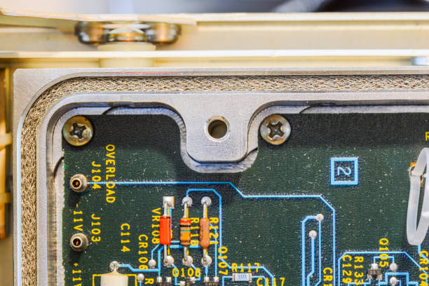
A reliable implantable PCB requires more than a visual inspection at the end of production.
Depending on the application, the qualification program may include:
- Dimensional inspection
- Automated optical inspection
- Electrical testing
- Microsection analysis
- Plated-hole evaluation
- Solderability testing
- Thermal cycling
- Humidity exposure
- Mechanical testing
- Coating integrity testing
- Aging studies
- Package or sealing verification
Not every test is required for every product. The appropriate qualification plan should be established according to the device’s intended use, risk profile, construction, and applicable medical-device requirements.
GOPCBA’s PCB Capabilities provide a useful foundation for evaluating fabrication requirements before production begins.
Common Material Selection Mistakes
Choosing Materials Solely Because They Are “Medical Grade”
A material being marketed as medical grade does not automatically mean it is appropriate for a specific PCB application.
The engineering team should determine:
- Where the material is located
- Whether it contacts the body
- Whether it is exposed to fluids
- Whether it is enclosed
- What sterilization process is used
- What electrical properties are required
- What mechanical loads are expected
Material selection should always be linked to the final device architecture.
Focusing Only on Thermal Performance
Temperature resistance is important, but it is not the only consideration.
A material may have excellent thermal stability while having unsuitable dielectric, mechanical, moisture, or processing characteristics.
A balanced evaluation is more effective than selecting materials based on a single specification.
Ignoring CTE Compatibility
Different materials expand and contract at different rates.
The PCB laminate, copper, components, package, adhesive, and enclosure may therefore experience different dimensional changes.
If these differences are not considered, repeated temperature changes can increase mechanical stress on solder joints, vias, interfaces, and coatings.
Over-Specifying the PCB
Using the most expensive or technically advanced material does not automatically produce a more reliable medical device.
Over-specification can increase:
- Material cost
- Manufacturing complexity
- Qualification requirements
- Supply-chain risk
- Production lead time
The objective should be to identify the lowest-complexity material system that reliably satisfies the actual device requirements.
From PCB Design to Production
Medical PCB projects benefit from early communication between the PCB designer, device engineer, materials engineer, packaging team, and manufacturer.
Before production, the engineering review should examine:
- PCB stack-up
- Material specifications
- Copper structure
- Via technology
- Mechanical dimensions
- Flexible or rigid requirements
- Surface finish
- Coating or encapsulation
- Electrical testing
- Reliability testing
- Traceability requirements
- Assembly compatibility
This integrated approach can identify manufacturability issues before they become expensive design changes.
A structured PCB Manufacturing Process and Reliability Design strategy is particularly valuable when PCB reliability is directly connected to the performance of a larger medical system.
Prototype Validation Before Volume Production
For implantable electronics, prototype production is an important engineering validation stage.
A prototype can be used to evaluate:
- Material compatibility
- PCB dimensions
- Electrical performance
- Component assembly
- Mechanical integration
- Coating or encapsulation
- Thermal behavior
- Manufacturing yield
Prototype results can then be incorporated into the production design.
This is especially important when the PCB uses specialized materials or construction methods that behave differently from conventional FR-4 boards.
For medical-device developers moving from prototype to production, Medical PCB Prototyping & Volume Production can be integrated into the overall manufacturing planning process.
Building a High-Reliability Implantable PCB
The development of an implantable PCB should ultimately follow a system-level reliability strategy.
A successful design does not depend on one special material. Instead, reliability comes from the interaction between:
- Appropriate substrate materials
- Stable conductor structures
- Reliable interconnections
- Effective moisture protection
- Mechanical compatibility
- Electrical integrity
- Controlled manufacturing
- Qualification testing
- Consistent supply and traceability
A High-Reliability PCB should therefore be engineered around the actual service conditions of the medical device.
For some products, flexible polyimide construction may be appropriate. For others, a rigid multilayer PCB inside a hermetically sealed enclosure may provide the better solution. Wireless devices may require specialized low-loss dielectric materials, while mechanically demanding systems may require flexible or rigid-flex architectures.
There is no universal material recipe.
Conclusion
Implantable medical electronics require a higher level of coordination between PCB design, materials engineering, packaging, manufacturing, and reliability testing.
The most important material-selection principles are not simply choosing the most expensive or most specialized material. Instead, engineers should evaluate the complete device architecture and determine which materials are required for electrical stability, mechanical performance, environmental protection, and biological safety.
Biocompatible PCB Materials may be necessary for specific exposed components or interfaces, while other internal PCB materials may be isolated from the body by qualified packaging.
At the same time, reliable fabrication remains essential. Precise lamination, drilling, plating, surface finishing, assembly, inspection, and traceability all contribute to the final performance of a Medical PCB.
By combining application-specific material selection with controlled Medical PCB Manufacturing, prototype validation, and appropriate reliability testing, medical-device developers can build electronic assemblies that are better suited to demanding long-term operating environments.