Elevator Control Board EMC: PCB Design, Manufacturing, and EMI Protection
Elevators are safety-critical transportation systems that must operate reliably under complex electrical and electromagnetic conditions. The control board acts as the central electronic system, receiving commands, processing sensor signals, controlling motor drives, managing door operation, and communicating with other elevator subsystems.
At the same time, elevator control boards are exposed to multiple sources of electromagnetic interference (EMI), including motor switching transients, variable-frequency drives (VFDs), power-line disturbances, relay switching, communication cables, and nearby electrical equipment. Poor EMC performance can result in communication errors, unstable sensor readings, processor resets, or unintended system behavior.
For this reason, elevator control board EMC should be considered throughout the PCB design, fabrication, assembly, and validation process rather than treated as a final-stage testing requirement.
A reliable solution combines appropriate PCB stackup and materials with controlled impedance, optimized routing, robust grounding, filtering, shielding, and comprehensive testing.
What Is EMC in an Elevator Control Board?
Electromagnetic compatibility (EMC) describes the ability of electronic equipment to operate correctly in its electromagnetic environment without generating excessive interference that disrupts other equipment.
For an elevator control PCB, EMC has two complementary objectives:
- Immunity: The control board must continue operating correctly when exposed to external electromagnetic interference.
- Emissions control: The control board must keep conducted and radiated emissions within applicable limits so that it does not interfere with other elevator electronics or nearby systems.
Elevator applications are particularly challenging because control electronics may share an environment with high-power motors, drives, relays, contactors, power cables, and communication networks.
Therefore, EMC performance depends on the entire electrical system—not just the PCB. However, PCB architecture and manufacturing quality have a major influence on the final result.
Key EMC Challenges for Elevator Control PCBs
An elevator control board commonly needs to manage several types of interference.
1. Conducted Electromagnetic Interference
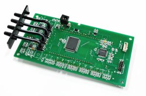
Motor drives and switching power supplies can introduce high-frequency noise onto power and signal connections. Without appropriate filtering and PCB grounding, this noise can enter sensitive circuits through connectors and power rails.
Potential consequences include:
- Microcontroller resets
- Communication errors
- Sensor instability
- Incorrect signal detection
- Unexpected system interruptions
Power-entry filtering, appropriate decoupling, controlled return paths, and careful PCB routing can reduce these risks.
2. Radiated Electromagnetic Interference
Elevator equipment often contains long motor cables, power wiring, encoder connections, and communication lines. These conductors can act as antennas and couple electromagnetic energy into sensitive PCB circuits.
High-speed digital signals and fast switching nodes can also generate radiation if their current loops are unnecessarily large.
3. Electromagnetic Emissions From the PCB
The control board itself can become a source of interference. Clock circuits, switching regulators, motor-control circuitry, and high-speed interfaces may generate electromagnetic emissions.
Good PCB design therefore needs to minimize high-frequency current loops and provide controlled return paths.
PCB Layout Strategies for Better Elevator Control Board EMC
EMC performance starts with the PCB layout.
Functional Zoning
A practical elevator control PCB can be divided into functional regions such as:
- Power input and protection
- Motor or drive interface
- Digital control
- Analog and sensor circuits
- Communication interfaces
- Safety-related circuits
High-noise switching circuits should be physically separated from sensitive analog and communication circuitry wherever the mechanical and electrical architecture allows.
For example, switching regulators, motor-control interfaces, and relay drivers should not be placed immediately beside low-level sensor inputs or precision analog circuitry.
Sensitive components such as ADCs, sensor amplifiers, oscillators, and communication transceivers should be positioned with their electromagnetic environment in mind.
Component Placement
Component placement should also minimize the physical size of high-frequency current loops.
Decoupling capacitors should be positioned close to the relevant IC power pins, with short connections to the power and ground network. Filtering components should be located close to the interface or noise source they are intended to control.
This approach helps prevent unwanted noise from propagating across the PCB.
For projects requiring detailed engineering support, a structured PCB design and layout process can identify EMC and manufacturability risks before production.
PCB Routing for Elevator EMC Performance
Routing is another critical factor in controlling electromagnetic interference.
Keep High-Current Loops Short
Motor-control and switching circuits can produce rapidly changing currents. The associated current loops should be kept as compact as practical to reduce parasitic inductance and radiated emissions.
Maintain Continuous Reference Planes
High-speed signal traces should have a continuous reference plane wherever possible. Interrupting the return path can increase loop area and create unwanted radiation.
Multilayer PCB construction can provide dedicated power and ground planes, improving return-current control and helping separate noisy and sensitive circuitry.
Differential Signal Routing
Differential signaling can improve immunity to common-mode interference when implemented correctly.
Encoder signals, communication interfaces, and other differential connections should be routed according to the requirements of the interface standard. Pair geometry, spacing, reference-plane continuity, vias, and connector transitions all affect signal integrity.
Differential routing does not automatically eliminate EMI; the complete signal path and common-mode behavior must also be considered.
Controlled Impedance
Where high-speed interfaces require impedance control, trace width, copper thickness, dielectric thickness, and the distance to the reference plane should be designed as a complete transmission-line structure.
The target impedance should be based on the interface specification and system design rather than applying a universal value.
For applications requiring controlled signal performance, selecting an experienced multilayer PCB manufacturer is important because fabrication tolerances can affect the final impedance.
Grounding and Return-Path Design
Grounding is one of the most frequently misunderstood aspects of EMC design.
For modern multilayer PCBs, a well-designed ground plane often provides a lower-impedance and more predictable return path than unnecessarily long discrete ground traces.
A solid ground structure can:
- Reduce return-path inductance
- Reduce loop area
- Improve signal integrity
- Limit unwanted coupling
- Support more predictable EMC performance
However, simply dividing the ground plane into multiple isolated sections is not always the best solution.
The grounding architecture should be based on current paths, circuit functions, isolation requirements, and the actual system topology.
For example, high-current switching returns should be prevented from sharing sensitive signal return paths in ways that introduce excessive voltage drops or common impedance coupling.
EMI Filtering at Elevator Control Board Interfaces
Connectors are potential entry and exit points for electromagnetic interference.
Power inputs, motor interfaces, encoder connections, and communication ports may require appropriate protection and filtering.
Common techniques include:
- Common-mode chokes
- Ferrite components
- Differential-mode filtering
- Transient protection
- Feedthrough capacitors
- RC filtering
- Appropriate connector shielding
- Cable shielding and termination
Filter selection should consider the operating frequency, signal bandwidth, current level, voltage rating, impedance, and required signal integrity.
An improperly selected filter can create new problems, such as signal attenuation, resonance, or excessive insertion loss.
Shielding for High-Noise Elevator Environments
Some elevator control applications operate close to powerful switching equipment and require additional shielding.
A metal shielding enclosure or local shielding can be used around particularly sensitive circuitry when system-level EMC analysis shows that it is necessary.
Effective shielding requires more than simply placing a metal cover over the PCB. The shield needs an appropriate electrical connection to the chassis or designated reference structure, and openings, seams, connectors, and cable penetrations must also be considered.
For PCB-level shielding, grounding via arrays can sometimes be used around designated regions to help control high-frequency coupling. Their spacing and placement should be selected according to the relevant electromagnetic wavelengths, PCB structure, and design objectives.
PCB Material and Stackup Considerations
Material selection can influence both signal integrity and reliability.
A conventional FR-4 construction may be suitable for many elevator controller applications. However, more demanding designs may require higher-Tg materials, specialized low-loss laminates, or other constructions depending on operating temperature, signal speed, layer count, reliability requirements, and electrical performance.
The stackup should be developed together with:
- Signal layers
- Ground planes
- Power planes
- Dielectric thickness
- Copper thickness
- Controlled-impedance requirements
- Thermal requirements
- Manufacturing capability
For complex boards, stackup optimization should be completed before detailed routing.
PCB Manufacturing Controls for EMC
Good EMC performance can be compromised by manufacturing variation if the PCB fabrication process is not tightly controlled.
Important manufacturing considerations include:
Copper Thickness
Copper thickness affects trace resistance, current capacity, thermal behavior, and controlled-impedance calculations.
Dielectric Thickness
The distance between a signal layer and its reference plane directly influences characteristic impedance and electromagnetic field distribution.
Etching Accuracy
Trace width variation can affect impedance and signal behavior, particularly in high-speed circuits.
Registration and Layer Alignment
Multilayer boards require accurate layer registration to maintain the intended electrical geometry.
Via Design
Via structures affect signal transitions, parasitic capacitance and inductance, and return-current paths. High-speed interfaces should minimize unnecessary via transitions.
A professional PCB manufacturing process should therefore include engineering review and manufacturability analysis before fabrication.
EMC Testing and Quality Control
EMC should be validated at both the PCB and complete-system levels.
Depending on the product architecture and applicable regulations, testing may include:
- Conducted emissions
- Radiated emissions
- Electrostatic discharge immunity
- Electrical fast transient/burst immunity
- Surge immunity
- Radiated RF immunity
- Conducted RF immunity
- Power-frequency magnetic-field immunity
- Voltage dips and interruptions
The exact test requirements depend on the elevator equipment classification, market, applicable standards, and complete system configuration.
PCB manufacturing quality inspection can include:
- Automated optical inspection (AOI)
- Electrical testing
- X-ray inspection where appropriate
- Dimensional inspection
- Solderability verification
- Visual inspection
- Impedance testing for applicable structures
- Material and process traceability
However, PCB inspection alone does not replace system-level EMC testing.
Prototype Validation Before Mass Production
For elevator control electronics, prototype validation is especially valuable because EMC problems can be expensive to correct after tooling, certification, and mass production have begun.
A prototype build can be used to evaluate:
- PCB layout
- Grounding architecture
- Filter performance
- Communication stability
- Sensor behavior
- Motor-drive interfaces
- Thermal performance
- EMC pre-compliance results
Engineering teams can then modify the PCB before releasing the final production version.
GOPCBA supports rapid PCB prototyping for engineering teams that need to validate PCB designs before moving into larger production volumes.
From Elevator PCB Prototype to Production
A reliable elevator control PCB supplier should be capable of supporting the project beyond the prototype stage.
The manufacturing partner should be able to manage:
- Engineering data review
- PCB fabrication
- Prototype production
- PCB assembly
- Electrical testing
- Functional testing
- Quality inspection
- Production documentation
- Batch manufacturing
- Traceability and delivery
This is particularly important for safety-related industrial electronics, where design changes and production variations need to be controlled.
When PCB fabrication and assembly are coordinated through one manufacturing workflow, engineering teams can also reduce communication gaps between the bare-board and PCBA stages.
For complete projects, turnkey PCB assembly can integrate component sourcing, PCB fabrication, SMT assembly, through-hole assembly, inspection, and testing.
Applications of EMC-Optimized Elevator Control PCBs
EMC-conscious PCB design can be applied across many elevator and vertical-transportation systems, including:
- Residential elevators
- Commercial elevators
- High-rise building elevators
- Hospital elevators
- Freight elevators
- Industrial lifting systems
- Elevator door controllers
- Motor-control systems
- Elevator communication modules
- Safety monitoring electronics
The exact PCB architecture depends on the elevator control system, motor technology, communication interfaces, safety architecture, operating environment, and applicable regulatory requirements.
How to Choose an Elevator Control PCB Manufacturer
When selecting an elevator PCB manufacturer, price should not be the only consideration.
Evaluate the supplier based on:
Engineering Capability
The manufacturer should understand multilayer PCB construction, impedance control, DFM, material selection, grounding structures, and manufacturing constraints.
Quality Management
Look for documented inspection procedures, process control, traceability, and appropriate quality certifications.
Prototype Capability
The ability to manufacture prototypes quickly can shorten the design-validation cycle.
Production Scalability
The supplier should be able to transition from prototype quantities to stable batch production without changing the manufacturing process unnecessarily.
PCB Assembly Capability
Integrated PCB assembly can simplify supply-chain management and reduce the coordination required between different suppliers.
Technical Communication
EMC issues often require cooperation between the PCB designer, manufacturer, component engineer, and system-level EMC engineer. A responsive manufacturing partner can help identify fabrication-related risks early.
Conclusion
EMC is a fundamental design consideration for elevator control boards because these systems operate in environments containing motors, variable-frequency drives, switching equipment, power cables, communication networks, and other potential sources of electromagnetic interference.
Reliable elevator control board EMC performance requires a system-oriented approach covering PCB layout, functional zoning, signal routing, return paths, grounding, filtering, shielding, stackup design, material selection, manufacturing control, and EMC validation.
The most effective strategy is to address EMC risks early during PCB design rather than attempting to correct them after production. Prototype testing can further reduce development risk and provide valuable feedback before mass manufacturing.
With professional PCB fabrication, assembly, inspection, and engineering support, elevator control electronics can achieve the electrical reliability and electromagnetic compatibility required for demanding industrial applications.