



HDI PCB: The Complete Guide to High-Density Interconnect Boards in 2026
Why HDI PCB Technology Matters in 2026
Electronics are getting smaller, faster and more capable every year. Smartphones, 5G base stations, medical imaging systems, ADAS modules and wearable devices all need more routing in less space. That is exactly where HDI PCB technology, or high density interconnect printed circuit boards, comes in. Compared with a conventional board, an HDI board uses microvias and fine line spacing to pack far more density into a compact form factor. For engineers and buyers, understanding how HDI works helps you choose the right board, control cost and avoid production surprises.
What Is an HDI PCB?
An HDI PCB is a printed circuit board built with high density interconnect structures. Instead of relying only on through holes, HDI boards use laser drilled microvias, blind vias, buried vias and via in pad features to connect layers in a compact stack. These features allow more routing channels per square centimeter and support very small pads and fine traces.
Typical HDI features include microvias of 150 microns or smaller, blind and buried via structures, sequential lamination to build up layers, and fine line and space capability. The result is a board that can carry a great deal of function in a much smaller area than a traditional multilayer design.
How HDI Technology Works
HDI boards are built layer by layer rather than drilled through the full stack. There are three core mechanisms that make high density routing possible.
Microvias and advanced via structures. A laser drills tiny holes that connect adjacent layers, then the holes are plated. Because these vias are so small, they can be placed directly on pads and routed densely. Blind vias connect an outer layer to an inner layer, buried vias connect two inner layers, and via in pad lets a via sit inside a solder pad, which is helpful for BGA and fine pitch devices. Shorter signal paths also reduce parasitic capacitance and improve signal integrity.
Sequential lamination. The board is manufactured using a build up process. A core is made first, then additional layers are laminated onto it in multiple passes. This sequential build up creates thin dielectric layers and supports the microvia structures that a single drilling step cannot achieve.
Fine line technology. HDI boards routinely reach line width and spacing of 50 to 75 microns. That level of precision suits high speed digital circuits and radio frequency applications, where tight impedance control and low loss matter.
Key Materials Used in HDI Boards
HDI boards depend on high performance materials to stay stable during lamination and in service. High Tg laminates improve heat resistance and prevent the board from moving at solder temperatures. Resin coated copper, or RCC, is used for thin dielectric layers so the build up stack stays thin. Low loss materials are chosen for high frequency and high speed signals where Dk and Df values affect performance. High performance prepregs layer the build up sections and bond them together. Together these materials give the board better signal integrity and longer term reliability.
HDI PCB Manufacturing Process
The production flow for an HDI board is more involved than a standard multilayer board. First the PCB is designed and the layout is optimized for the stack up. Next the cores and build up layers are laminated, then microvias are laser drilled. The holes are cleaned and plated with electroless copper followed by electroplating, before via filling and surface planarization make the surface flat for the next layer. The board then goes through repeated lamination cycles to reach the final layer count. Pattern transfer and etching define the fine traces, and a surface finish such as ENIG or OSP protects the copper. Finally the board is electrically tested and inspected before it ships. An experienced partner runs each step with tight tolerances so the board performs predictably.
Advantages of HDI PCB
Higher routing density. More functions fit in the same board area, so you can eliminate a daughtercard or reduce the overall system size. Better electrical performance. Shorter paths in microvias reduce delay and electromagnetic interference, which is critical for high speed buses. Smaller and lighter. Compact boards are ideal for portable and wearable devices where weight matters. Improved signal integrity. Fine line and controlled impedance support high speed and RF designs with cleaner signals. Higher reliability. The build up structure and via in pad design reduce failure points and support long term dependability.
HDI PCB Applications
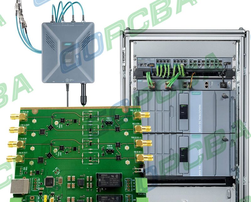
HDI boards are used wherever space, speed and reliability are at a premium. Smartphones and tablets rely on them for dense logic and memory. 5G communication equipment needs HDI for high frequency front ends and antennas. Wearable electronics pack sensors and radios into very small outlines. Automotive electronics, especially ADAS and electric vehicle control units, use HDI for high density signal processing. Medical devices such as monitors and imaging systems demand consistent performance and small size. These fields all push the limits of density and performance, which is why they turn to HDI.
HDI vs Conventional PCB
The main structural difference is the via type. HDI uses microvias and build up layers, while a conventional board is dominated by through holes drilled through the whole stack. This changes performance. HDI supports high speed and high frequency signals better because vias are shorter and the routing is tighter. Conventional boards are cheaper per board and easier to manufacture, but they cannot reach the same density.
HDI costs more per unit, yet it can lower the total system cost by shrinking the board, reducing layer count and avoiding a second board. Choose HDI when the product needs high speed signals, compact design, high integration or a smaller finished device.
HDI PCB Design Considerations
Stack up design. Optimize the number and distribution of layers so the board meets impedance targets without unnecessary cost. Signal integrity control. Match impedances, manage return paths and reduce crosstalk between dense traces. Thermal management. Use thermal vias and conductive structures to move heat away from power devices and high speed ICs. Design for manufacturing. Keep trace widths, via sizes and spacing within the capabilities of the fabricator so the board is easy to build at volume. Partnering with an experienced manufacturer early ensures the design is manufacturable and cost effective.
HDI PCB Cost in 2026
HDI pricing depends on layer count, structure complexity, number of microvias, material type, surface finish and order size. As a rough reference, a 2 to 6 layer HDI prototype typically ranges from about 120 to 500 US dollars, while a complex 8 to 12 layer board can run from 500 to over 1500 US dollars. In high volume production, HDI often falls into the 0.05 to 0.25 US dollars per square centimeter range. To lower cost, optimize the stack up, avoid unnecessary microvias and choose standard materials where possible.
How to Choose an HDI PCB Manufacturer
When comparing vendors, look at real HDI capability: microvia drilling, fine line resolution and sequential lamination. Check certifications such as ISO and IPC, confirm the delivery cycle, and review the quality control system. Consider customization and engineering support as well. A strong HDI partner offers advanced manufacturing technology, fast prototyping in as little as 24 to 72 hours, strict quality control and reliable global delivery so your project moves quickly and repeatably.
For manufacturing and engineering support, start with PCB manufacturing and review PCB design and manufacturing best practices to make sure your stack up and layout are production ready. When density is your priority, HDI is the path to explore.
Future Trends in HDI Technology
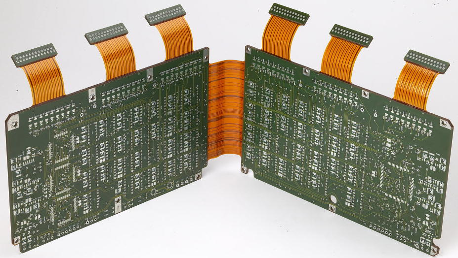
HDI will keep evolving. Artificial intelligence and high performance computing are pushing demand for more layers and finer lines, and edge devices need more routing in smaller footprints. Ultra low loss materials are being adopted for faster signals. Higher layer counts and finer lines are becoming routine, and HDI is increasingly combined with flexible and rigid flex construction. HDI will remain a core technology for advanced electronics as these trends continue.
FAQ
What is the difference between an HDI PCB and a normal multilayer board? An HDI board is a multilayer board, but it uses microvias and a high density interconnect structure to reach higher routing density and better signal performance.
Is an HDI PCB more expensive? Yes, it costs more per board, but the performance gains and smaller size can lower the total system cost.
Which industries use HDI PCB most? Communication, consumer electronics, automotive electronics and medical devices are the largest users.
How do I design an HDI PCB? Use an EDA tool and follow DFM rules, and work with a specialist manufacturer to validate the stack up and tolerances.
Get the Right HDI Solution
HDI PCB technology is moving electronics toward smaller, faster and more powerful products. Its high density interconnect capability and strong electrical performance make it essential for modern designs. If you want to stay competitive in 2026, HDI is a strong choice. With advanced HDI manufacturing, fast prototyping and cost effective volume production, a specialist partner can help you bring your compact, high performance product to market quickly. Compare stack options in our HDI microvia structure guide to see how 1N1 and 2N2 builds differ.
