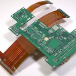
PCB Design Factors: Layers, Vias, Silkscreen and Pads
Most layout problems trace back to a handful of concepts that are easy to use without understanding. A pad that was placed as a default, a via that was copied across the board, a copper pour that was drawn as a rectangle because it looked tidy: none of these will fail a design rule check, and all of them will cause trouble later. This article works through the PCB design factors that repay attention during the layout.
Layers Are Copper, Not Drawings
The first conceptual step is to remember that a layer in a PCB file corresponds to a physical sheet of copper. Everything drawn on a signal layer becomes metal, everything drawn on a mask layer becomes an opening in a coating, and nothing drawn on a mechanical layer becomes anything at all unless the fabricator is told what it means. Confusing the drawing layers with the copper layers is the source of a whole family of errors, from missing pads on a footprint to silkscreen printed across a solderable area.
Once the layer count is fixed, disable the layers that will not be used. A drawing that shows traces on a layer that does not exist in the stackup will be manufactured as if it did not exist, and the mismatch is usually found only after the boards arrive.
Vias: Size, Count and Clearance
Vias connect layers, but they also occupy space on every layer they pass through and they interrupt the reference plane beneath the signal above them. Two habits follow. First, keep the number of vias on a critical net small, because each one is a discontinuity and a stub. Second, check the clearance between a via and any copper that it is not connected to on the layers it crosses, including planes, because a via that passes within a few tenths of a millimetre of a plane can create a capacitively coupled defect that no netlist test will find. Via to trace clearance in multilayer boards covers the spacing rules in detail.

Current capacity also sets via size. Power and ground connections need larger vias, or several small ones in parallel, because a single small barrel has a higher resistance and a lower current rating than the trace that feeds it. Placing four 0.3 mm vias where one 0.6 mm via will not fit achieves the same result.
Silkscreen That Survives Assembly
Silkscreen is not decoration; it is the information the assembler and the repair technician rely on. Two rules keep it useful. The marking must not be printed over a pad or a paste opening, because it reduces the solderable area and can interfere with the stencil. And it must remain legible after the parts are fitted, which means an orientation mark on the side of the component that the operator can see rather than directly underneath it.
Keep reference designators consistent and avoid moving them by hand unless the automatic placement is genuinely ambiguous. On a dense board it is better to delete a designator than to print it over a neighbouring part.
Surface Mount Parts and Side Assignment
Surface mount devices belong to a specific side of the board, and the footprint library entry has to say which. A part assigned to the wrong side produces a footprint with no pins on the layer where the copper is, which is the classic missing-pad error. Text associated with the part follows the same rule: the marking belongs to the side the part sits on.
If the design needs parts on both sides, plan for two reflow passes and keep the second side limited to small, light components. A heavy part on the underside of a board that will be reflowed a second time is a rework risk even when the paste holds it in place.
Copper Pour: Mesh or Solid
A copper pour can be drawn as a solid area or as a grid of intersecting lines. The solid version carries more current and shields better, but it is more prone to warping during lamination on a large area and it can be harder to solder if it is left without thermal reliefs. The mesh version adheres better, drains better during processing, and behaves less like a large heat sink, which matters on a hand-soldered board. Copper flooding: mesh or solid sets out the trade-offs in more detail.
Whatever the pattern, a pour that is not connected to a net is worse than no pour at all, because it acts as an antenna. Connect every pour to ground or to a defined potential, or remove it.

Pad Selection and Sizing
Pads are usually taken from the component library without a second look, and that is where many assembly defects begin. The pad has to suit the component body, the lead form, the soldering process and the mechanical stress the joint will see. A component that vibrates or that is used as a test point needs more pad area than the drawing suggests, and a part whose leads carry current needs a pad large enough to dissipate the heat.
Two practical numbers: the drilled hole should be 0.2 to 0.4 mm larger than the lead diameter for a through-hole part, and the annular ring should be wide enough to survive the drill tolerance. PCB pad design standards gives the geometry for common package families.
Mask Layers and Their Meaning
The solder mask layer defines the openings in the coating, and the paste mask layer defines the openings in the stencil. They are complementary rather than identical: the paste opening is usually slightly smaller than the copper pad on a fine-pitch part and slightly larger on a part that needs more solder. Getting this wrong produces joints that are starved or bridged, and the error is invisible until the first assembly run.
The Ratsnest as a Layout Tool
The ratsnest, the web of straight lines showing unrouted connections, is the most useful guide to placement. Before routing, move components until the ratsnest shows the least crossing and the shortest total length, and the routing will then be straightforward. The same display shows which connections remain unrouted after an autoroute, which is where manual routing effort is best spent. Treating the ratsnest as a nuisance rather than as feedback is one of the most common reasons a layout takes longer than it should.
It also exposes placement mistakes early. A single ratline crossing the whole board usually means a component is on the wrong side of the design, and a cluster of ratlines converging on one area often means a functional block has been split. Both are cheap to fix while the placement is still fluid and expensive to fix once the routing has been started around them.
FAQ
Should every unused layer be disabled? Yes. Disabling unused layers removes the possibility of drawing on a layer that will not be manufactured and makes the design rules easier to check.
Is a solid copper pour always better than a mesh? No. Solid pours carry more current and shield better, but mesh pours adhere better, drain better and behave less like a heat sink. The choice depends on the function of the area.
How much clearance should a via have from a plane? Enough that the drill tolerance and the registration budget cannot bring the barrel into contact with the plane. The value depends on the fabricator’s capability, so it should be taken from their design rules rather than assumed.