Rigid-Flex Manufacturing Process: Steps and Tolerances
A rigid-flex board is not a rigid board with a flexible tail glued on. It is a single construction in which rigid and flexible sections are laminated together and permanently interconnected, which means the process has to satisfy the requirements of both. That combination creates a specific set of manufacturing steps and tolerances, and understanding them is what allows a designer to write a stackup that can actually be built.
What Makes Rigid-Flex Different
In a rigid board the laminate is rigid everywhere, the panel can be handled and pressed with normal tooling, and the outline is a single cut. In a rigid-flex board part of the construction is thin, unsupported and free to move, so everything that touches the panel during processing has to be able to cope with a section that is a fraction of a millimetre thick.
The result is that rigid-flex manufacturing concentrates on handling and registration rather than on finer features. The critical capabilities are not line width but the ability to keep a thin, floppy section aligned through lamination, drilling and plating.
Material Selection for the Flexible Sections
Flexible sections are built on polyimide film with an adhesive system that can survive lamination and repeated bending. The adhesive choice matters as much as the film, because a flexible core with a brittle or thick adhesive layer will crack at the bend. Adhesiveless constructions are preferred for dynamic flexing, and the copper on a dynamic section is usually rolled annealed rather than electrodeposited, because its grain structure tolerates bending far better.
Laser Contour Cutting
The flexible outline is often cut with a laser rather than a router, particularly where the shape is complex or the material is thin. Laser contour cutting gives a clean edge without the mechanical stress of routing, but it is a thermal process, and the parameters have to be matched to the material so that the cut edge is not charred or recast.
The layout consequence is that the edge of a flexible section should be simple enough to cut cleanly, and the designer should not place features so close to the flex outline that the heat-affected zone reaches them.
Selective Plating and Surface Finish
selective plating allows a finish to be applied to one area of a panel while another area is masked. On a rigid-flex board it is used where a connector tab needs a hard finish and the rest of the board needs a solderable one, and it is also used to protect the flexible section from chemistries that would damage it.

The process adds steps and requires the mask to be accurate, which is why the areas that need a different finish should be defined on the fabrication drawing rather than left to the shop to infer.
Plasma Desmear and Etchback
polyimide does not behave like epoxy during drilling. The resin smears onto the hole wall and is harder to remove with conventional permanganate chemistry, so a plasma step is normally used for desmear, and often for etchback as well. plasma desmear cleans the hole wall and prepares it for plating; etchback removes a controlled amount of resin so that the copper layers protrude slightly into the barrel, which improves the connection.
Both are dry processes with parameters that have to be tuned to the material. Too little plasma and the barrel plating will not adhere; too much and the hole wall is over-etched and the barrel becomes thin at the layer interfaces.
Material Dimensional Tolerance
Polyimide and its adhesives move more during lamination than rigid laminate, and they move differently in the machine direction and across it. That movement accumulates across a large panel, so the registration budget for a rigid-flex board is larger than for an equivalent rigid stack.
The practical response is to keep the flexible section short in the direction where registration is critical, to avoid placing fine-pitch features at the far end of a long panel, and to agree the dimensional tolerance with the fabricator before the layout is fixed. PCB dimensional stability explains how the movement is characterised.
Thin Material Handling
Handling is the least visible and most frequent source of loss on these builds. A flexible section is easily creased, and a crease in a plated area becomes a crack. Panels are therefore supported with carrier boards, processed in frames, and moved with fixtures rather than by hand.
For the designer this translates into layout rules: keep the flex section clear of unnecessary copper, avoid plated features in the region that will bend, and keep the bend radius generous. A bend radius of at least ten times the total thickness is a common starting point for a static bend, and much larger for a dynamic one.
The Construction Sequence
The build starts with preparing and cleaning the laminate, which includes removing the protective coating from the copper and micro-etching the surface to give the resist a key. The circuit pattern is then produced, either by screen printing an etch resist or by photoimaging a dry film, and the pattern is etched.
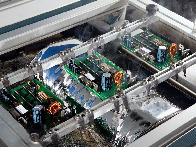
The flexible and rigid layers are then laid up with bonding layers, pressed, and the rigid sections are drilled and plated through. Where a flexible section must not be plated or coated, it is protected with a mask or a coverlay before the wet processes. The final steps are the outer imaging, the solder mask or coverlay, the finish, and the profile cutting that separates the boards.
Design Rules Worth Fixing Early
Bend Area Rules That Cannot Be Relaxed
The bend area is where rigid-flex boards fail, and the rules that protect it are different from the rules used anywhere else on the board. No plated through holes should sit in the bend region, because the barrel is a rigid cylinder inside a material that will be flexed. Copper in the bend should be as thin as the design allows, with wide traces rather than narrow ones, and the traces should run perpendicular to the bend line so that the stress is distributed along their length rather than concentrated across a corner.
Coverlay and stiffeners are part of the same discipline. A coverlay protects the conductors and defines the bend, and a stiffener bonded to a rigid section keeps a connector or a component from stressing the flexible material underneath it. Both are features that have to be drawn explicitly, because the fabricator will not add them by default. Recording the bend line and the bend radius on the fabrication drawing turns an implicit expectation into an instruction.
Six decisions determine whether a rigid-flex design is manufacturable: the layer stack for each section, the bend radius and its position, the materials including the adhesive system, the finish on each area, the tolerances the design actually needs, and the panel arrangement. Blind and buried via stack selection covers how the via structure interacts with the layer stack, and Multilayer PCB prototype requirements lists the inputs the fabricator needs to quote and build the first article.
FAQ
How tight can the bend radius be? For a static bend, ten times the total thickness is a common guideline; for a bend that will flex repeatedly, the radius has to be much larger and the copper has to be rolled annealed.
Why is plasma used instead of chemical desmear? Because polyimide smear resists the conventional permanganate process. Plasma removes it reliably and can also be used to control etchback.
Can a rigid-flex board use standard design rules? For the rigid sections, mostly yes. For the flexible sections, the rules for copper, coverlay and bend geometry replace them and should be taken from the fabricator’s capability sheet.