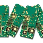
Mouse PCB Design: Sensor Interface, Buttons and Radio
A computer mouse is a small product with a surprisingly dense board. It contains an optical sensor with a very high data rate, a microcontroller that polls it thousands of times a second, several switches that produce mechanical noise, a radio and an antenna if it is wireless, and a battery with its charging circuit if it is rechargeable. All of that fits into a board shaped to the underside of a hand.
This article covers what goes on a mouse PCB, how the sensor and the input circuits should be laid out, and the mechanical constraints that shape the board.
What Is on a Mouse PCB
The functional blocks are consistent. An optical sensor captures a stream of surface images and computes the displacement between them. A microcontroller reads that data, samples the switches and the wheel, and sends the result to the host. A radio transmits it for a wireless mouse, and a power section manages the battery and the charging.
The board is usually a single or double-sided design with a rigid main section and a flexible tail that carries the side buttons and the battery connection. That mix of rigid and flexible circuit construction is what allows the shape to fit the housing without a connector in the middle, and the layout has to plan the transition from the beginning.

The Optical Sensor and Its Interface
The sensor is the highest-speed device on the board and the one most sensitive to layout. It communicates with the microcontroller over a synchronous serial interface, often at several megahertz, and it also has its own supply and reference requirements. The manufacturer datasheet normally specifies the decoupling and the recommended layout around the sensor, and those recommendations should be followed rather than adapted.
The optical path is part of the layout as well. The sensor looks through an aperture in the board or in the housing, and the lens and the light guide have to be positioned so that the illumination reaches the surface and the reflected image reaches the sensor. Copper and solder mask near the aperture change the reflection and can degrade tracking, so the area around the optical opening should be treated as a controlled zone. The mixed-signal layout rules apply to the interface and the supply, because the sensor is an analogue device with a digital output, and its supply is shared with a switching regulator.

Button Input and Debouncing
A mechanical switch does not close cleanly. The contacts bounce for a few milliseconds, producing a burst of transitions that the microcontroller would otherwise interpret as multiple clicks. The debounce can be implemented in firmware, with a resistor and capacitor, or with a dedicated device, and the choice affects the layout only slightly but the feel of the product considerably.
Capacitive debouncing uses a capacitor across the switch and a series resistor, forming a time constant long enough to absorb the bounce. The capacitor has to be placed close to the switch pin, and the resistor in series with the input, so that the trace between them is short and does not pick up noise. Where the switch is on a flexible tail, the components usually sit on the rigid section and the tail carries only the switch, which keeps the flex simple and the board area free.
Radio, Antenna and Battery
A wireless mouse has a 2.4 GHz radio with an antenna that is usually printed on the board or on the flexible tail. The antenna needs a copper-free keep-out area and a solid reference plane, exactly as in any other radio design, and the keep-out has to be checked against the battery, which is the largest metal object in the product.
The battery is often the dominant mechanical constraint. It sits under the board or beside it, and its position determines where the antenna can go and how much copper area is available for grounding. Placing the battery between the antenna and the user’s hand is a common arrangement because the hand absorbs radiation, but the keep-out still applies and the antenna cannot be inside the battery outline.
Polling Rate and Latency
The polling rate is how often the sensor reports position, and it sets the latency between a movement and its appearance on screen. A high polling rate means a fast serial interface, which means the trace between the sensor and the microcontroller has to be treated as a high-speed connection rather than a slow one.
At multi-megahertz clock rates the trace should be short, referenced to a continuous ground plane, and kept away from the switch inputs and the power supply. Where the interface runs across the rigid-to-flex transition, the ground return has to cross it as well, and the via design rules determine how the reference plane is stitched through the bend so the return path stays continuous.
Mechanical Integration and the Flex
The shape of the board follows the housing, which means the layout is a mechanical exercise as much as an electrical one. The mouse buttons are usually part of the top shell and press on switches mounted on the board or on a daughter flex, and the position of those switches is fixed by the shell geometry rather than by the layout.
Where the design uses a flexible tail, the tail has to be specified with a bend radius it can survive for the number of assembly operations and the number of times the product is opened. The coverlay construction and the trace direction through the bend follow the standard rules, and the coverlay design guidance covers the openings and the adhesive behaviour that keep the tail reliable.
Design Rules for a Mouse Board
Keep the sensor interface short and referenced to a solid plane, and follow the sensor manufacturer’s layout recommendations exactly. Keep the switch inputs away from the radio and the sensor interface, and filter them at the pin. Keep the antenna keep-out free of copper, battery and hands. Provide test points for the sensor supply and the serial interface, because a mouse that will not track is otherwise difficult to diagnose.
Plan the ground as a single continuous structure. On a small board with a radio, an optical sensor and a switching supply, the ground is the only thing that keeps the three from interfering with each other, and a ground that is cut into islands by the layout will produce intermittent behaviour that is hard to reproduce.
FAQ
Does a mouse PCB need a controlled-impedance stack? The radio feed line does, and it is usually a short 50 ohm microstrip or coplanar line. The sensor interface benefits from a solid reference plane but rarely needs a defined impedance at the distances involved.
Why does a wireless mouse need a flex tail? To reach the side buttons and the battery without a connector. A flex carries the switches at positions fixed by the housing and folds into the assembly, which removes a connector and two solder joints from the product.
Can the antenna be printed on the flex tail? It can, and it is a common arrangement, but the tail must be positioned so the antenna is clear of the battery and of the user’s hand. The keep-out applies wherever the antenna is placed.