Remote Control PCB Design: Antenna, Power and Input
A remote control is a small radio with a keypad attached, and it lives under constraints that make it harder to design than its size suggests. It runs from a coin cell or a pair of AAA cells for a year or more, it has to transmit reliably from the far corner of a room, and it has to survive being dropped, sat on and left in a hot car. Remote control PCB design is the discipline of satisfying all three at once.
What the Board Contains
The core is a microcontroller that scans the keypad, encodes the command and controls the transmitter. Alongside it sits the radio or infrared module, a small antenna or an infrared emitter with its driver, the battery and its power path, and a set of contacts that turn a physical keypress into an electrical signal.
Higher-end designs add an LED indicator, a regulator or a boost converter to hold a stable supply as the battery drains, and electrostatic discharge protection on the contacts that a user will touch. The component count is low, which means the layout of those few parts determines almost everything about performance.
RF, Infrared, Bluetooth and Wi-Fi Variants
An infrared remote modulates a carrier around forty kilohertz and needs a clear line of sight to the receiver. Its board is simple and its cost is low, which is why it still dominates in televisions and air conditioners, but it cannot pass through an obstruction and it is directional by nature.
A radio remote typically operates in a licence-free band and can work through walls and from any orientation. A Bluetooth or Wi-Fi remote adds a protocol stack, which means certification and a more capable microcontroller, and it brings the possibility of firmware updates and two-way communication. Each step up in capability adds design work rather than only component cost.
Antenna Placement
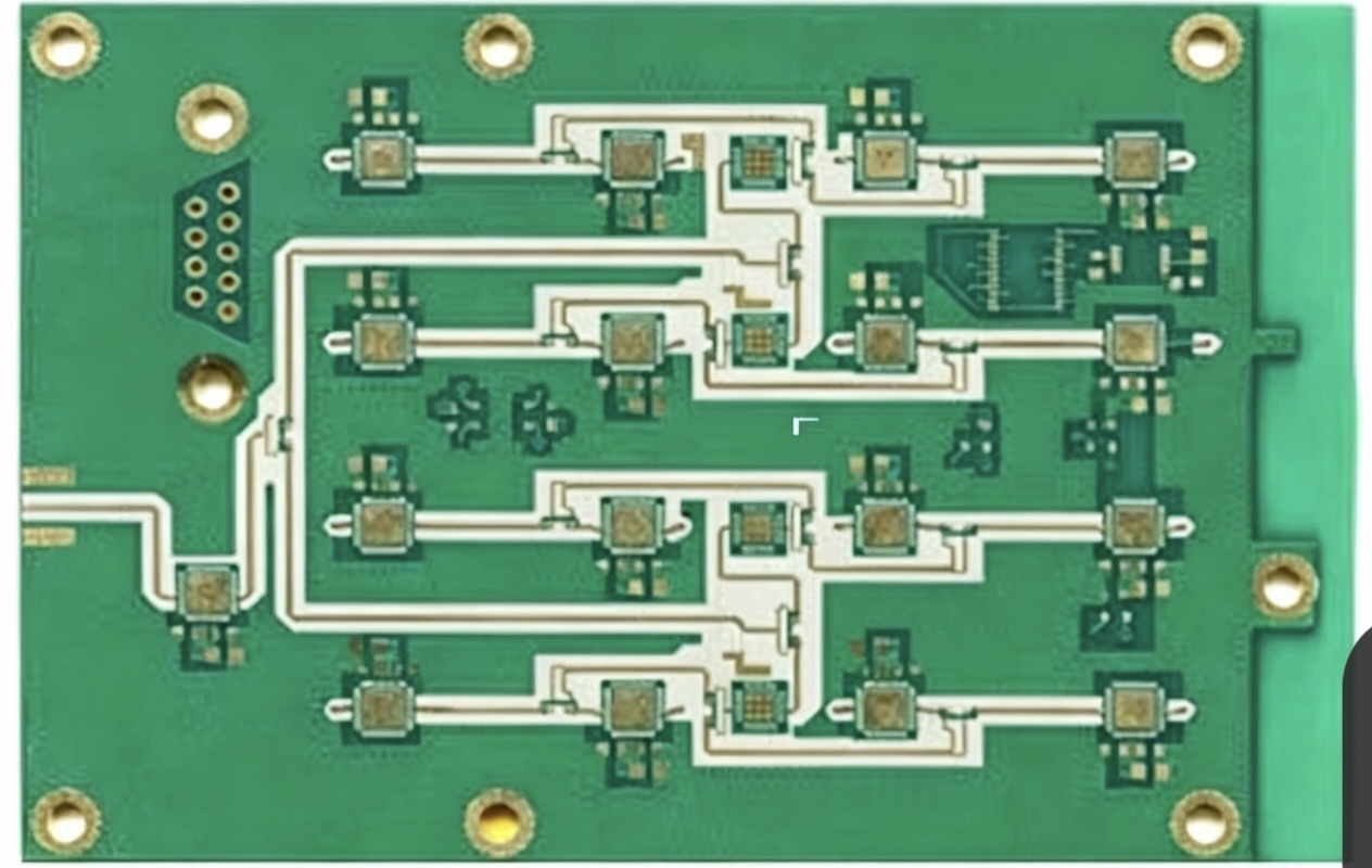
Antenna placement is the single most consequential decision on the board. The antenna needs a ground plane reference but must not sit on top of one, so the region beneath and around it is kept free of copper on every layer. Placing it at the board edge or, better, overhanging the edge, gives the most predictable radiation pattern.
Hand and body proximity detune a small antenna, and on a remote control the user is holding exactly that. Designing the keep-out area, the ground plane extent and the board outline together is what makes the difference between a reliable link at ten metres and one that works only at three. The mechanical constraints involved are covered in the notes on board outline and mounting design.
Power Budget and Sleep Modes
Battery life is arithmetic. The average current is the transmit current multiplied by its duty cycle, plus the receive or standby current, plus the sleep current of every component on the board. A remote that transmits for twenty milliseconds when a key is pressed spends almost all of its life asleep, so the sleep current dominates the calculation.
sleep mode therefore has to be designed rather than assumed. Leakage through a pull-up resistor, a regulator with poor quiescent current or a floating input that oscillates can each consume more than the radio. Measuring the standby current on the first prototype and tracing it back to the component responsible is worth more than any specification review.

Button Contacts and Input Design
Two approaches dominate. A carbon or metal dome pressing onto interdigitated contacts on the board is cheap and robust, and it needs the contact pads sized so that the resistance stays low even after thousands of presses and a little surface contamination. A capacitive keypad removes the mechanical contact entirely and gives a sealed surface, at the cost of sensitivity to moisture and to the user’s gloves.
Either way, the input path needs protection. A user touching a remote in a dry room can generate a discharge that reaches the microcontroller, so series resistance, a transient suppressor or at least a well-designed path to ground belongs on every exposed contact. The general approach to routing that survives discharge events is described in the notes on ESD protection and edge traces.
Material Choice
Most remote controls are built on ordinary FR-4, and that is entirely adequate for an infrared design or a low-power radio. Where the board carries a radio at higher frequency, a low-loss material reduces the loss in the feed path and stabilises the impedance, which improves both range and consistency between units.
The trade is cost and process. A low-loss laminate costs several times a standard one, and it machines differently, so it is justified only where the link budget is genuinely tight or where the design has to hold its tuning across production. On a high-volume consumer remote it is rarely the right answer.
Mechanical and Environmental Reality
A remote control is dropped onto hard floors, compressed under cushions and left on a dashboard in summer. Those conditions set requirements the schematic never mentions: the board needs stiffening or mechanical support where it is thin, connectors and batteries need retention that does not rely on solder alone, and the surface needs protection against the oils and cleaning agents it will encounter.
A conformal coating protects the assembly from humidity and contamination, but it must not cover the keypad contacts or the antenna matching network, where it would change the electrical behaviour. Masking those areas is part of the process design rather than something added afterwards.
Common Field Failures
The most frequent complaint is reduced range rather than total failure. That usually traces to an antenna that was placed slightly differently from the reference design, a ground plane that extends further under it than intended, or a battery whose internal resistance has risen and whose terminal voltage now sags during transmit.
Intermittent operation is usually mechanical, stemming from a cracked solder joint on a component that is stressed when the case flexes, or from contamination on the keypad contacts. Complete failure points to a microcontroller or transmitter fault, which on a well-designed board is rare and usually the result of an electrostatic discharge event reaching the input pins.
Testing Before Volume
Functional test on a remote is mostly a radio measurement plus a power measurement. Output power, frequency accuracy and modulation quality tell you whether the radio is working; average current in sleep and in transmit tells you whether the battery will last. Both are better measured on a small sample before production than inferred from the datasheet.
Range testing should be performed with the board in its final enclosure and held as a user would hold it, because the case and the hand both affect the antenna. A board that passes on the bench and fails in a hand is a design that was validated in the wrong condition.
FAQ
Can a remote control board use a chip antenna instead of a wire? Yes, and many do. A chip antenna is smaller and easier to assemble, but it needs a well-defined keep-out and a matching network, and its efficiency is generally lower than a wire or printed antenna of the same size.
Why does my remote only work from a few metres? The most common causes are an antenna keep-out that is smaller than the design requires, a ground plane that extends under the antenna, or a battery whose voltage sags under the transmit current pulse.
Is a low-loss laminate needed for a 433 MHz remote? Rarely. At that frequency the loss in a short feed path on ordinary FR-4 is small, and the money is better spent on the antenna geometry and the ground plane design.