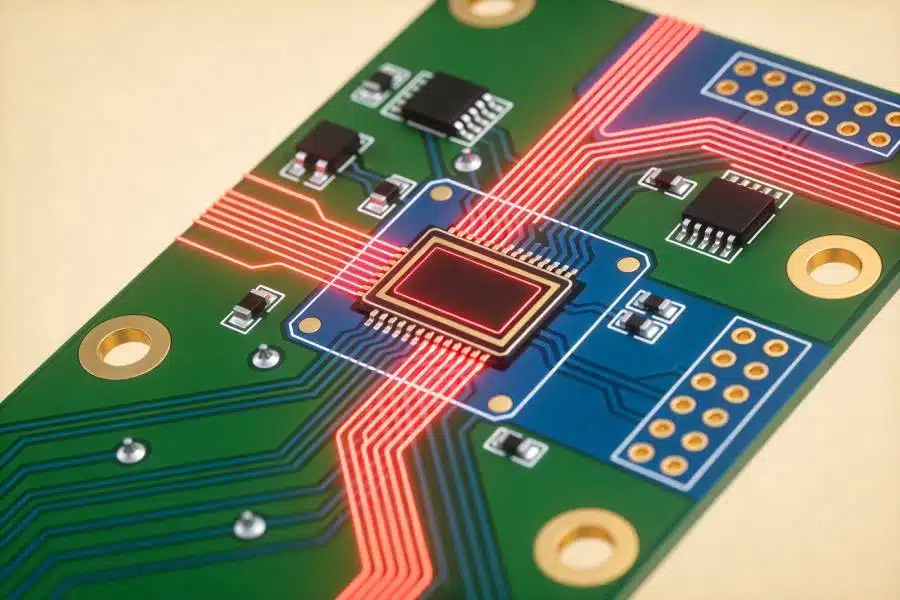
Space Grade PCB Manufacturing: Reliability Above All
Hardware that leaves the atmosphere cannot be repaired, which changes every engineering decision on the board. A space grade PCB is specified not to perform well on average but to survive every foreseeable condition, and the manufacturing discipline that follows is closer to aerospace quality assurance than to commercial electronics production.
What Makes Space Hardware Different
Three conditions define the environment. The thermal cycle is severe, with hardware moving between deep cold and direct solar heating as it orbits or changes attitude. The vacuum removes convection as a cooling mechanism and causes materials to release trapped volatiles. And radiation introduces ionising effects that degrade semiconductors and, at high enough doses, insulation.
To that add the impossibility of service. A failure mode that would be an inconvenience on Earth becomes a mission loss, so designs are conservative and verification is exhaustive.
Outgassing Control
In vacuum, absorbed moisture and volatile organic compounds leave the laminate and the coatings, and the released material can condense on optical surfaces, thermal radiators or sensors. The effect is both a contamination problem and a change in the properties of the materials that remain.
Material selection is therefore restrictive. Laminates, solder masks, adhesives and coatings are screened for total mass loss and collected volatile condensable material, and only materials with accepted test data are permitted. Where suitable screening data does not exist, the material is generally excluded rather than tested on the critical path.
<img src="https://www.gopcba.com/wp-content/uploads/2026/09/14.webp" alt="Space grade PCB panel prepared for thermal vacuum qualification” />
Thermal Vacuum and Cycling Qualification
Thermal vacuum testing reproduces the combination of vacuum and temperature extremes. The assembly is cycled between limits, often for hundreds of cycles, and inspected afterwards for cracks, delamination and changes in electrical parameters.
Plated through holes are the most common failure point, because the laminate expands in the z-axis far more than the copper barrel. A high glass transition temperature material, adequate barrel plating thickness and a plating process that produces ductile copper are all required, and the qualification test is what proves they worked together.
Laminate and Material Choices
Polyimide laminates are common in space hardware, chosen for their thermal stability and their ability to tolerate repeated cycling without degradation. Where electrical performance demands it, specialised low-loss materials are used, subject to the same outgassing screening.
Copper weight is often heavier than in commercial designs, partly for current capacity and partly for thermal spreading, and the surface finish is selected for long-term stability rather than for assembly convenience.
Workmanship and Acceptance Class
Space hardware is normally built to Class 3 workmanship requirements as defined by IPC or an equivalent program-specific standard, which tightens the acceptance criteria for annular ring, plating thickness, hole wall quality and surface defects. Acceptable imperfection is much narrower than in commercial production.
Inspection follows accordingly: microsections from every panel or from a defined sample plan, coupon testing for impedance and plating, and a documented review of every deviation before the hardware advances. Serialisation of individual boards is normal.
Radiation Considerations
The board itself contributes to radiation tolerance only indirectly, but its layout matters. Shielding provided by copper layers, spacing between sensitive nodes and the avoidance of thin dielectric where high voltage appears all reduce susceptibility to total dose and single event effects.
Where the program requires it, the board design works alongside component selection and, in some cases, local shielding. The layout should not introduce a weak point that the component screening was intended to avoid.
Traceability and Documentation
Every process step is recorded and tied to the serial number of the assembly. Material lots, plating bath chemistry records, lamination parameters, inspection results and operator identification are all part of the delivered data package.
This is not bureaucracy for its own sake. When an anomaly appears during integration, the ability to trace a specific board back to a specific material lot and process run is often the only way to determine whether the problem is isolated or systemic, and the general quality framework applied here is described in the guidance on design quality characteristics.
Design Practices for Reliability
Design conservatively. Use larger annular rings than the minimum, avoid the smallest features the process can produce, and design the stackup with thermal expansion in mind rather than only for routing convenience. Redundancy in the ground and power distribution costs little and improves both electrical and thermal performance.
Then design for inspection. Coupons on every panel, test points that survive coating and a documented acceptance plan make it possible to demonstrate that the manufactured hardware matches the qualified design. Reviewing copper plating defect prevention is worthwhile given how often the barrel is the limiting element, and the manufacturing sequence itself follows design and fabrication practice adapted to aerospace acceptance criteria.
Cleanliness and Contamination Control
Residue that would be harmless on a commercial board can become a failure mechanism in space. Ionic contamination left after soldering can promote corrosion and, under bias in a humid environment during ground testing, electrochemical migration. Flux residue can also release volatiles over time.
Cleaning processes are therefore specified rather than optional, and cleanliness is verified by measuring ionic contamination on a sample. Assembly areas are controlled for humidity and particulate contamination, and handling procedures limit contact with bare board surfaces.
Conformal coating is applied only after cleanliness is verified, since coating over residue traps the contamination in place. The coating itself must be an approved low-outgassing material, and the application method must reach under components without leaving voids.
Derating and Design Margin
Derating is the practice of operating components and conductors below their rated limits, and in space hardware it is applied systematically rather than as a matter of judgement. Resistors run at a fraction of their power rating, capacitors at reduced voltage, and conductors at reduced current density so that the temperature rise stays conservative.
The same principle applies to the board itself. Annular rings are larger than the minimum, dielectric spacing exceeds the electrical requirement where space allows, and vias are sized for reliable plating rather than for density. Each choice costs area and none of them shows up as a performance benefit on the bench.
What they provide is margin against the unknowns: a temperature that runs hotter than predicted, a material property that varies between lots and a transient that exceeds the analysis. On hardware that cannot be serviced, margin is the cheapest form of insurance available.
Verification Flow From Design to Flight
Verification begins with a design review that checks the derating calculations, the material list against the approved database and the coupon plan for the panel. It continues with first article inspection and qualification testing on representative hardware, and it ends with a data package that accompanies the boards through integration.
Each stage assumes the previous one was completed honestly, which is why the records matter as much as the tests. A qualification test on a board whose material lot was substituted without documentation proves nothing about the hardware that actually flew.
FAQ
Can a commercial board be used in space? Sometimes, for a short mission with relaxed requirements, but the material screening and workmanship criteria usually rule it out. Outgassing alone disqualifies most standard solder masks and adhesives.
Why is polyimide preferred over FR-4? It maintains its mechanical properties across a wider temperature range, which matters when the assembly experiences hundreds of cycles between extremes. FR-4 can be used in some applications, but it provides less margin.
What is the most common cause of failure in space boards? Plated barrel cracking from thermal expansion mismatch, followed by contamination from outgassing materials. Both are addressed by material selection and process control rather than by design changes after the fact.