LED Lighting PCB Basics: Substrate, Thermal Design and Layout
An LED luminaire lives or dies by its thermal path, and the printed circuit board is the first link in that path. Unlike a logic board, an LED board feeds a continuous current into devices that turn much of it into heat rather than light, so the board has to be designed as a thermal component as much as an electrical one. The substrate, the copper and the layout together decide the junction temperature, and the junction temperature decides how long the fixture lasts.
Where the Board Sits in the Thermal Chain
Heat leaves the die through the die attach, the package pad, the solder joint, the copper of the LED lighting PCB, the dielectric, the base and finally the heat sink and the air. Each link has a thermal resistance and the largest one sets the temperature rise of the whole assembly. In a great many designs that largest term is the dielectric layer under the pad, not the copper and not the heat sink.
That is why the substrate decision comes early. A board with thick copper above a hundred micrometre organic dielectric runs hotter than a board with thinner dielectric on a metal base, even though the second board carries less copper. Organic dielectrics are two orders of magnitude worse conductors than metal, so their thickness dominates everything else in the stack.
Board Types for Different Power Levels
Single sided FR4 suits indicator lamps and low power strips, where the forward current per device is a few tens of milliamps and the case temperature stays modest. As power rises, a metal core PCB with an aluminium substrate becomes the standard solution, because the metal spreads heat sideways and gives the assembly a stiff, flat face that can be clamped to a heat sink.
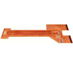
Flexible boards appear where the light source follows a curved surface or where the fixture is very thin, and they use polyimide with thin copper foil. Double sided and multilayer constructions are chosen when the driver shares the board with the emitters, since the control circuit needs a ground plane and its own routing. Mixing power and control on one board works, but the ground strategy has to be settled before layout rather than repaired afterwards.
Substrate, Copper and Dielectric Selection
Copper thickness sets both current capacity and lateral spreading. One ounce copper, thirty five micrometres, is enough for small lamps; two or three ounce copper is common where a string carries several amps, and it also lowers the spreading resistance under each emitter pad. Heavy copper is not free, because etch tolerance and minimum gap grow with thickness and a design needing fine spacing cannot always use it.
The dielectric between copper and base is the parameter worth arguing about. Its thermal conductivity is published by the supplier, and one to three watts per metre per kelvin is typical for the better materials. Thinner is better thermally and worse for dielectric strength, so the choice has to be made against the isolation requirement of the product rather than against the thermal target alone.
Junction Temperature and the Thermal Calculation
The design target is the junction temperature of the emitter, not the temperature of the board, and it should be calculated rather than measured after the fact. The calculation adds the resistance from junction to case, through the solder joint to the pad, through the dielectric to the base, and from the base to ambient. Suppliers publish each term, and their sum shows whether the fixture can meet its life target.
A useful rule of thumb is that ten degrees of extra junction temperature can halve the expected life of a phosphor converted emitter, and it also shifts the colour point. Running the stack at nominal current and at worst case ambient, then confirming that the worst case still meets the lifetime target, costs far less than discovering the problem during qualification.
Thermal Vias and Their Limits
Where no metal base is used, a thermal via array under the pad is the alternative. The vias carry heat through the board to a copper area on the far side. Their benefit is limited by the plating thickness in the barrel and by the small cross section of each hole, so a useful array needs many vias at a tight pitch rather than a few wide ones.
Filling the vias changes the result. An open via has a poor thermal path, while one filled with copper paste and capped conducts far better and gives a flat surface for the solder joint. The trade off is process cost, and the through via discussion in via in pad or plated through applies to lighting boards exactly as it does to other thermally demanding packages.
Routing, Current Sharing and Voltage Drop
Parallel strings do not share current equally unless the layout makes them. Two branches of different length have different resistance, so the shorter branch takes more current, runs hotter and drifts further from its neighbours. Symmetric branches, or a constant current source per branch, keep the output uniform and stop one string from ageing faster than the rest.
Trace width follows from the current and the permitted temperature rise, using the same calculation as any power board, and wide traces also cut the voltage drop along a long strip that matters when one driver feeds a chain of modules. The method is set out in trace width and current calculation.

Solder Mask, Finish and Environmental Protection
Mask colour affects more than appearance. White mask reflects light that would otherwise be lost and lifts the optical efficiency of the fixture, but it yellows under ultraviolet and heat, so its reflectance falls over service life. Black mask gives higher inspection contrast and suits dark housings, at the cost of absorbing stray light and adding a little heat.
The finish governs the quality of the joint on the thermal pad. A finish that oxidises quickly, or that leaves a rough surface, produces voids under the pad, and voids directly spoil the thermal path. Immersion gold and immersion tin both give a flat, solderable surface, and the choice follows from storage time and assembly process rather than from the emitter. Outdoor fixtures add humidity and condensation to the list, so a conformal coating is often specified, as described in conformal coating and board protection.
Manufacturing and Assembly Notes
Metal core panels are machined rather than routed in the usual way, and aluminium burrs, so outline and slot processes have to control them. Panelisation must leave enough material for handling, because a thin metal panel bends more easily than FR4 and a bent panel will not print solder paste evenly across the array.
Reflow has to respect the thermal mass of the board. A metal core board draws heat out of the joint during reflow, so the profile needs a longer soak or a higher peak than a thin FR4 equivalent, and the paste must be selected for that profile. Assemblies that combine a metal board with a daughter card meet the same problem twice.
Reliability Expectations
The common failure modes of a lighting board are thermal cycling fatigue at the solder joint, delamination of the dielectric and discolouration of the mask. All three depend on the temperature swing rather than on the absolute temperature, which is why a fixture switched on and off several times a day ages differently from one that runs continuously.
Tracking a field failure back to the design usually points at an undersized thermal path, an asymmetric current distribution or a dielectric chosen for cost rather than for the swing. Each is visible in a calculation at design time and each is expensive to correct once tooling exists.
FAQ
What copper thickness should a metal core PCB use? One to two ounce copper on the circuit layer covers most fixtures, and two to three ounce where a string carries several amps. Thicker copper helps spreading, but it also raises the minimum gap that the etcher can hold.
Do thermal vias work on ordinary FR4? They help, but the improvement is limited because the barrel plating is thin and the dielectric still dominates. For high power emitters a metal base is usually the better answer.
Is a flexible board suitable for high power lighting? Rarely. Polyimide boards have thin copper and no metal base, so they suit decorative and low power applications where shape matters more than heat.