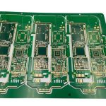
Injection Molding Machine Control PCB: Current, Heat and Noise
An injection molding machine is a hydraulic press with a temperature problem. Its control board has to sequence the clamp, hold several heating zones along the barrel, drive the servo pumps that meter the melt, and read pressure and temperature signals accurately enough to repeat a shot to within a fraction of a gram.
Those functions place contradictory demands on a single board. The heating zones draw tens of amperes, the servo drives switch in microseconds, and the thermocouple and load cell signals beside them sit in the millivolt range. Layout is what keeps those worlds apart, and this article covers the injection molding machine control PCB decisions that matter most.
What the Board Has to Drive
A typical control board carries the logic and the low level analog section, while the heaviest current is distributed through contactors or solid state relays mounted on a separate heat sink. Where the drive electronics do sit on the board, each axis is a three phase inverter with its own DC bus capacitor and gate driver, and the bus is usually fed from one rectifier shared by all of the axes.
The input and output side is equally demanding. Digital inputs read limit switches, position sensors and safety interlocks, digital outputs drive solenoid valves and indicators, and analog inputs read thermocouples, RTDs, pressure transducers and position feedback. All of that wiring arrives from a cabinet full of cables that carry switched current.
<img src="https://www.gopcba.com/wp-content/uploads/2026/08/pcb-1.png" alt="Injection molding machine control PCB with heavy copper power section” />
Heavy Copper for Current
Trace width follows the current and the permitted temperature rise, not the convenience of the layout. A 20 A trace carrying continuous current in 2 oz copper needs on the order of 200 mil of width to stay below a 10 degrees C rise, and the calculation has to be repeated for every section of the path rather than for the net as a whole.
Where the copper becomes impractical, the design changes instead of the trace width. Inner layer copper is raised to 3 or 4 oz, bus bars are bolted to the board, or the current is routed through a laminated copper bar. Solder joints are kept away from the hottest runs because the joint has a lower melting point and a different thermal expansion coefficient than the copper beside it.
Thermal Path from the Power Modules
Gate drivers, rectifiers and shunt resistors all dissipate heat into a small area, and that heat has to reach the enclosure rather than the adjacent components. Arrays of thermal vias under each module, copper on both sides of the board and a defined contact area with the chassis are the standard measures, together with enough spacing to keep the electrolytic capacitors out of the hot zone.
Electrolytic capacitors set the service life of the whole assembly, because their expected life roughly doubles for every 10 degrees C reduction in core temperature. Placing them upstream of the air flow, or shielding them from the rectifier, is often the cheapest reliability improvement available on an industrial board.
Isolation and Noise Immunity in a Factory
Industrial cabinets are electrically hostile. A 400 V bus on one side of the board and a 5 V sensor interface on the other means the creepage and clearance rules are the first constraint on the layout, and gate drive signals crossing that boundary are routed through digital isolators with their own isolated supplies.
Immunity is designed at the interfaces. Analog inputs receive series resistance, a capacitor to chassis and a transient suppressor; communication ports are filtered and, where the cable leaves the cabinet, isolated. Sensor returns are never shared with power returns, and the two meet at one defined point near the converter that reads them.

Temperature and Pressure Sensing
Thermocouple inputs are differential, low level and easily corrupted. The connection point is kept isothermal so that the cold junction compensation measures the terminal block rather than a gradient across the board, and the traces from the connector to the amplifier are short and matched so that any parasitic thermocouple junction is small and symmetric.
Load cell and pressure signals are handled the same way, with a Kelvin connection to the bridge and a stable reference for the converter. Input filtering is set to reject 50 or 60 Hz while still allowing the sample rate the control loop needs, and the anti alias filter is placed before the converter rather than implemented in firmware.
Reliability, Coating and Service Life
An industrial control PCB spends a decade in a cabinet that sees vibration, humidity and temperature cycling. Conformal coating over the high impedance nodes, locking connectors, wide clearance between the mounting holes and any copper, and a board outline that resists flexing when a heavy cable is pulled are all part of the specification rather than optional extras.
gopcb produces these boards with heavy copper capability, controlled impedance for the servo interfaces and the process documentation that an industrial customer needs to qualify a supplier. Every design starts from the drive currents and the sensor accuracy targets, because those two numbers decide the copper weight, the layer count and the grounding scheme.
Cabinet Integration and Wiring Practice
The board never works in isolation; it works inside a cabinet with contactors, transformers and variable frequency drives. The mounting arrangement decides how much heat leaves through the chassis and how much arrives from the devices beside it, so the thermal management plan starts with a survey of what surrounds the board and where the air actually moves.
Wiring practice then sets the electrical environment. Screened motor cables are terminated with the shield bonded to the cabinet, signal cables are routed separately from the drive cables, and the analog and the digital sections of the board are fed through separate connectors so that a technician can isolate one without disturbing the other during service.
Design Review Checklist
Before release, confirm the current in every power path against the copper width and the permitted temperature rise, list which components share a thermal path, and check that the isolation distances between the drive side and the sensor side satisfy the applicable standard. Then confirm that each analog input has its own filtered return.
Finally, review what the machine has to do when something fails. A control board that reports a failed thermocouple instead of reading it as a cold barrel prevents a scrap batch, and the hardware that supports that diagnostic, a bias current source and a range check, costs almost nothing when it is designed in at the schematic stage.
Related reading: trace width and current calculation, DC-DC converter layout and routing, high temperature PCB materials, and ground current and harmonic distortion.
FAQ
How much copper weight does a molding machine control board need? Most designs use 2 oz copper with 3 or 4 oz on the high current layers. The choice follows the continuous current and the allowed temperature rise, and it is usually cheaper to add copper weight than to add a bus bar.
Why is isolation such a large part of the layout? Because the DC bus, the gate drives and the sensor front end must be separated by creepage and clearance distances defined by the applicable standard. That distances dominate the layout before any routing begins.
Should the thermocouple circuit use a separate ground? It should use a separate return that meets the main ground at one point. Sharing a return with a valve driver puts switching current through the sensor reference and shows up immediately as temperature noise.