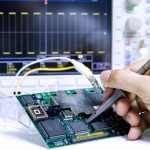
Infrared Thermometer PCB Design and Thermopile Sensors
An infrared thermometer is a small system with an unusually demanding analog front end. The detector produces a signal in the microvolt range, the ambient temperature drifts over tens of degrees, and the whole measurement has to complete in about a second. The board that carries that chain decides whether the reading is accurate, and the decisions that matter are mostly about noise, thermal gradients, and grounding rather than about the display.
How an Infrared Thermometer Works
Every object above absolute zero radiates infrared energy, and the amount radiated depends on its temperature. An infrared thermometer measures that radiation without touching the object. The optical path collects energy from a defined field of view and delivers it to a detector, which converts it into an electrical signal. Because the instrument never contacts the surface, it avoids the thermal mass and the contamination problems of a contact probe, and it can measure a moving target or a sterile surface.
That non-contact measurement is the whole point of the architecture, but it also imports a set of error sources that a contact probe does not have. The reading depends on the emissivity of the target, on the distance from the instrument, and on the temperature of the instrument itself. The electronics have to correct for the last of these explicitly, because the detector measures a difference, not an absolute value.
Contact and Non-Contact Architectures
Contact designs, such as an ear thermometer, place a probe against the measurement site. The assembly typically contains a probe with an infrared waveguide, a thermopile detector, the main circuit board, a display, a buzzer, and a battery. The waveguide carries radiation from the measurement site to the detector, and the detector converts radiant power into a voltage that the electronics linearize into a temperature.
Non-contact designs, such as a forehead thermometer, use an optical assembly instead of a waveguide: an infrared window, a lens or mirror, the main board, a display module, and the housing. The measurement is fast, usually about a second, and requires no skin contact, which is the property that made these instruments ubiquitous in public screening. The trade-off is that the reading depends strongly on distance and on the emissivity of the surface, so the optics and the firmware both have to enforce a viewing distance.
<img src="https://www.gopcba.com/wp-content/uploads/2025/05/未标题-6.jpg" alt="Infrared thermometer PCB with thermopile sensor and analog front end” />
The Thermopile Sensor and Its Interface
Most of these instruments use a thermopile sensor: a silicon device that converts temperature differences into a voltage through the Seebeck effect. Two characteristics dominate the board design. The output is small, often tens of microvolts per degree, so any noise on the input is comparable to the signal. The second is that the device measures a temperature difference between the target and the sensor body, so a reference temperature measurement is required, and the two readings have to be combined before a result can be displayed.
The sensor also has a defined field of view, which is set by an aperture and sometimes by a filter. A narrow viewing angle makes the instrument suitable for measuring small targets at a distance, while a wide angle averages a larger area. That choice is optical, but it constrains the board: the aperture has to be aligned to the detector to within a fraction of a millimeter, which means the mechanical mounting of the sensor board is part of the measurement accuracy.
Signal Conditioning for a Microvolt Signal
The conditioning chain has one job: turn a very small differential voltage into a number without adding error. That usually means a low-noise amplifier with high gain placed as close to the sensor as the mechanics allow, followed by an analog-to-digital converter with enough resolution to preserve the result. Because the signal is small and the gain is large, the input offset of the amplifier and its drift with temperature become part of the measurement, so an amplifier with low offset drift is worth more here than one with a lower noise floor.
The ambient temperature measurement is the other half of the chain. The thermopile reports the difference between the target and its own body, so the body temperature must be measured independently and added back. A sensor placed close to the thermopile, on the same thermal mass, gives a reference that tracks the detector rather than the room. Where the two are separated, a thermal gradient between them appears directly as a temperature error, and it develops slowly, which makes it invisible in a bench test and obvious in the field.
Layout Rules for the Analog Front End
The front end deserves to be treated as an analog island. Keep the amplifier input traces short and symmetric, and run them over an unbroken ground plane. Guard the input with a ring tied to the same reference the amplifier uses, and keep the digital section, the display driver, and the buzzer away from it, because those are the largest noise sources on the board and the ones most likely to couple into a high-impedance input; the remedies overlap with low-cost signal quality improvements.
Two details are specific to this class of instrument. First, every solder joint between dissimilar metals is a thermocouple, and in a circuit that resolves microvolts, a few joints at slightly different temperatures generate an offset that looks exactly like signal. Keep the input connections thermally symmetric and avoid unnecessary joints in the input path. Second, do not place the amplifier where the regulator or the backlight will warm it; self-heating in the analog section shifts the offset and appears as a slow drift. General guidance on partitioning the two domains appears in mixed-signal PCB design guidelines.
<img src="https://www.gopcba.com/wp-content/uploads/2020/12/project_image_08-1.jpg" alt="Ambient temperature compensation sensor placed beside the thermopile” />
Sources of Measurement Error
Four error sources dominate in practice. Emissivity is the largest: a surface that reflects more than it emits reads low, which is why a polished metal target cannot be measured reliably without a correction or a matte patch. Distance is the second, because the field of view widens with distance and begins to include the background, so the instrument is only accurate inside the spot size its optics define. Ambient drift is the third, and it is the one that ambient temperature compensation exists to remove. Self-heating is the fourth, and it comes from the board itself.
There is a fifth that surprises designers: the display board is part of the instrument. If the backlight, the regulator, and the analog front end share a small board with no thermal separation, the heat they produce reaches the reference sensor and shifts the reading by an amount that depends on how long the unit has been switched on. Spacing the heat sources away from the sensing area, and letting the instrument stabilize before the first measurement, addresses both.
Design Checklist
Before release, confirm that the reference temperature sensor sits on the same thermal mass as the detector. Confirm that the input traces are short, symmetric, and guarded. Confirm that the aperture in the housing aligns with the detector to within the tolerance the optics require. Confirm the ground scheme, because the analog return and the digital return must meet at a single point. Finally, confirm that the finished board will be protected against the humidity it will see in use, since leakage across a contaminated surface is a first-order error on a high-impedance input; the options are compared in conformal coating for board protection.
FAQ
Why does the sensor need a separate ambient measurement? Because a thermopile reports the difference between the target and its own body. Without the body temperature, that difference cannot be converted into an absolute reading.
Why is emissivity a problem with metal targets? A reflective surface emits less than an ideal radiator and reflects its surroundings, so the radiation it sends back no longer corresponds to its temperature alone.
What makes a reading drift after switch-on? Self-heating. The regulator, the display, and the analog circuitry warm the reference sensor, so the correction changes until the unit reaches thermal equilibrium.
Why guard the amplifier input? Because the input is high impedance, and leakage current across a contaminated or damp surface appears as a voltage error comparable to the signal itself.