
PCB Silkscreen Design: Line Width, Clearance and Marking
Silkscreen is the layer of the design that people read. It identifies the components, marks the orientation of the parts that can be fitted the wrong way, warns about handling restrictions and carries the identifiers that link a board to its documentation.
It is also the layer that is most often treated as an afterthought. A legend that is printed at a resolution the process cannot hold, or that overlaps a pad, produces an assembly problem that no electrical test will catch.
What the Legend Has to Do
The primary function is assembly support. A placement operator or a machine needs to know which part goes where, which end of a diode is the cathode and where pin one of an integrated circuit sits. The legend provides that information visually, and it has to survive the assembly process to be useful.
The secondary function is traceability. A board part number, a revision code and a date or lot code printed on the board link the physical unit to its documentation, and they are frequently the only durable record once the packaging is discarded.
Line Width and Print Resolution
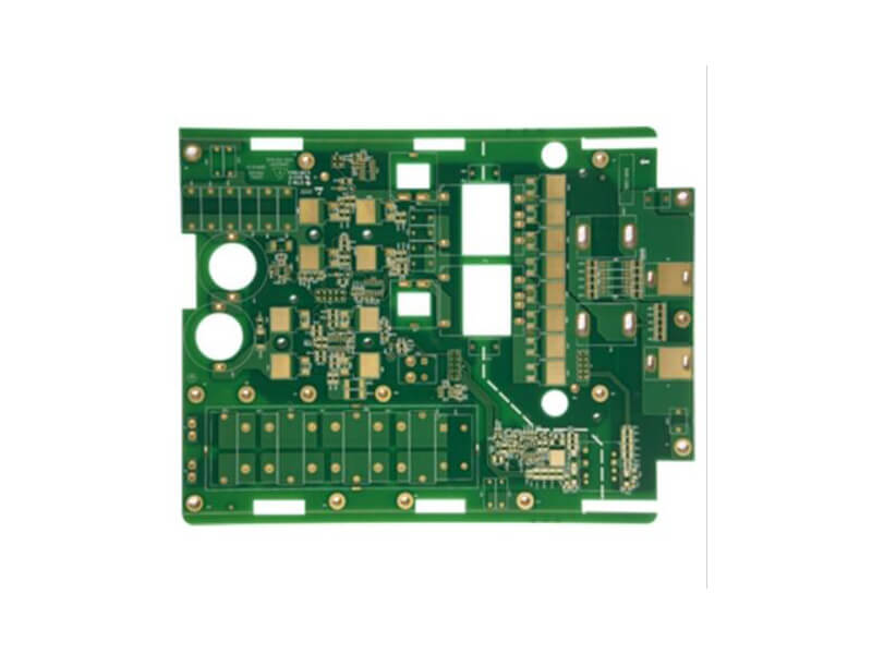
Silkscreen is printed through a screen or with an inkjet process, and the resolution is limited by that method rather than by the artwork. A typical process holds a minimum line width of 0.15 mm and a minimum character height of 0.8 mm, while finer legends are possible with a more demanding process.
Legibility matters more than minimum feature size. A line that is printed at the limit of the process has ragged edges that make the characters harder to read, so most designs use a line width somewhat above the minimum except where space forces otherwise.
Clearance to Pads, Mask and Board Edge
The legend must not print on a pad. Ink over a solderable surface interferes with wetting and is a defect, so the silkscreen artwork is checked against the mask openings with a clearance that reflects the print registration tolerance rather than the artwork tolerance.
The same applies at the board edge, where ink that crosses the routed outline flakes or smears during depaneling. A clearance of at least the router tolerance from the outline prevents the legend from being damaged or from producing debris in the machine.
Reference Designators and Assembly
Designators should be placed where an operator can read them with the board in its assembly orientation, not where the schematic placed them. A common practical rule is to keep the designator beside its component, aligned with the board edges, and outside any area that a connector, a shield or a heat sink will cover.
On a dense board it is often impossible to place every designator legibly. The usual compromise is to print the ones that matter for manual assembly and to provide the rest in the assembly drawing, rather than to print a dense field of unreadable text.
Polarity, Orientation and Pin One
Orientation marks are the most valuable part of the legend. A polarity bar on a diode, a chamfered corner or a dot for pin one on a package, and a plus sign for a polarized capacitor all reduce the chance of an assembly error that functional test may not detect.
The mark has to be unambiguous. A pin one dot that is the same size as a via mask opening is not a mark, it is a coincidence, and a legend where two interpretations are possible will eventually be read the wrong way.
Legend Over Different Finishes
The colour of the legend and its contrast depend on the solder mask. White on green is the classic combination and gives good contrast, while white on white, or a light legend on a black mask, reduces readability and increases the inspection difficulty for automated equipment.
The type of ink also matters. A legend printed before the final finish has to survive the plating and the surface finish chemistry, which is why the sequence is specified by the fabricator rather than chosen freely.
Panel Marks and Traceability
Beyond the single board, the panel carries marks of its own: the panel part number, the fabricator’s lot code, a date code and sometimes a barcode. These are used through the manufacturing process to link a board to the panel, the panel to the lot and the lot to the material.
Where a customer requires traceability, that data is often printed as a two dimensional code that can be read automatically. Its position is chosen so that it survives the depaneling and the assembly, which usually means keeping it away from the edges and from the areas under connectors.
Documentation and Common Defects
The silkscreen layer belongs in the fabrication drawing together with the ink colour and the minimum line width. Where the legend has been adjusted for assembly, that adjustment should be recorded, so that a later revision does not restore a designator that was deliberately removed.
The defects that recur are ink on pads, characters printed below the legible line width, legends that have flaked at the board edge and designators hidden under a taller component. gopcb produces boards with validated silkscreen resolution and clearance checks against the mask, so the legend that the design intends is the legend that the assembly line sees.
Legend, Mask and Assembly Process Interaction
The legend sits on top of the solder mask, so its behaviour depends on what the mask does. Over a mask defined pad the ink can be printed close to the opening, while over a copper defined pad the mask dam between the pad and the legend is narrow and the ink can slump into the opening during cure. That slumping is the mechanism behind most reported ink on pad defects, and it is prevented by clearance rather than by inspection.
The ink also interacts with the surface finish. A legend printed before an immersion finish is exposed to the chemistry and must resist it, while ink printed afterwards sits on a surface that may already carry the finish. The sequence is the fabricator’s decision, but the designer should know which one applies, because it changes the minimum feature size that can be held reliably and the appearance of the finished board.
Reviewing a Legend Before Release
A legend review is a short exercise with a high return. Check that no ink crosses a mask opening, that every polarized component carries a polarity mark on the correct side, that pin one is marked on every multi pin package in a way that cannot be confused with a via, and that every designator is legible at the process minimum.
Then check the practical questions. Is any designator hidden under a connector, a shield can or a heat sink once the board is assembled? Does the legend survive the depaneling at the board edge? Is the traceability code positioned where it can still be read after assembly? Those four questions account for most of the legend problems that reach production, and each of them is cheaper to answer on the screen than on the line.
FAQ
What is the minimum legible text size? Around 0.8 mm in character height with a 0.15 mm line width on a standard process. Smaller text can be printed but becomes unreadable and is more likely to be defective.
Can silkscreen print over a via? Over a tented via, yes, provided the mask surface is sound. Over an open or plugged via, the ink fills the hole and produces an uneven surface, so it should be avoided.
Why does ink sometimes flake off the board? Usually because the legend was printed over a surface that was not clean or not fully cured, or because it crosses an area that is later machined. Both are process issues rather than artwork issues.
Related reading: PCB manufacturing processes, PCB design quality characteristics, PCB manufacturing tolerances, and board outline and mounting design.