




PCB Copper Plating and Via Filling: How They Differ
Copper plating and via filling are often discussed as if they were alternatives for the same requirement. They are not. Plating deposits a thin layer of copper on the wall of a drilled hole to make an electrical connection, while filling replaces the empty volume of the hole with a material so that the surface above it can be flat.
Understanding the difference matters because the two processes are chosen for different reasons, they are controlled by different parameters and they fail in different ways.
Two Different Objectives
Plating exists to connect the layers that the hole passes through. The copper has to be continuous, well adhered and thick enough to carry the current and to survive thermal cycling. The centre of the hole remains empty.
Filling exists to close the hole. The objective is a surface that can be plated over and used as a pad, which is what a via in pad design requires, or a barrel that is completely occupied for thermal conduction. The electrical connection is established by the plating step that follows or precedes the fill.
Copper Plating in the Barrel
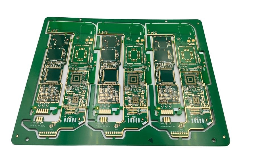
The plating process begins with a thin electroless copper layer that makes the hole conductive, followed by electrolytic plating that builds the thickness. The result is a copper sleeve with a specified minimum thickness, commonly 20 to 25 micrometres in a standard board and more where the current or the thermal cycle demands it.
The thickness is verified by cross section, because the copper at the middle of a thick board is thinner than at the surface. The plating thickness is also measured on the surface, where it is easier to control, and the two measurements are related by the throwing power of the bath.
Aspect Ratio and Throwing Power
The aspect ratio is the board thickness divided by the drill diameter, and it describes how difficult the hole is to plate. A high ratio means the plating solution has to penetrate further, and the copper at the centre of the hole builds more slowly than at the ends.
Throwing power is the ability of the chemistry to deposit evenly over that depth. Where the aspect ratio exceeds the capability of the process, the mid barrel copper is thin, and the plating may be porous or cracked. It is the most common reason a design has to increase the hole size or reduce the board thickness.
Via Filling with Conductive Material
Filling is usually performed with a conductive or non conductive paste applied by screen printing, or with a plating process that is run long enough to close the hole from both sides. Plating a hole closed is possible only for a small diameter, which is why the process is associated with microvias rather than with standard through holes.
Paste filling can close a larger hole, but the result is a filled via with a plug rather than a solid copper barrel. The material has a different thermal conductivity from copper, so the fill serves the planarity requirement well and the thermal requirement only partially.

Plating Versus Filling for Thermal Vias
A thermal via needs both properties: a connection and a path for heat. Plating provides the connection and a limited thermal path, since the copper is a thin sleeve with a void inside. Filling with a conductive material improves the thermal path, but the improvement depends on the conductivity of the fill.
The most effective thermal via is a plated hole that is then filled with copper by plating, which produces a solid copper column. That is technically demanding, and where it is not available a large array of plated vias with a conductive fill is the practical alternative.
Process Control and Measurement
The plating line is controlled through the chemistry, the current density and the agitation. The copper thickness in the hole and on the surface is measured on a coupon, and the plating quality is confirmed by a cross section that also shows the adhesion to the laminate.
The filling process is controlled through the paste viscosity, the stencil, the cure profile and, for a plated closed via, the plating time. The critical measurement is the presence of voids, which is assessed by cross section, and the flatness of the surface, which is assessed on the finished panel.
Choosing the Right Approach
Where the requirement is a connection between layers and the hole can remain open, plating is the answer and it is the default for every through via on the board. Where the requirement is a flat surface for a component, filling is added on top of the plating.
Where the requirement is thermal, the choice depends on the heat flux. A large array of plated vias connected to a plane handles a moderate flux; a filled and capped via improves it; and a copper coin or a metal core board is used when even that is insufficient.
Defects and Their Causes
The plating defects are a thin or porous barrel, a crack from thermal cycling and a separation between the plating and the laminate. The filling defects are a void inside the plug, a surface that is not flat enough for placement and a material that outgasses during reflow.
gopcb controls barrel plating thickness with coupon verification and offers filled and plated over vias with defined void limits, so the connection and the flatness requirements are met by a controlled process rather than by chance.
Interactions Between the Two Processes
The two steps are not independent, because the filling process sits between plating operations in the flow. A via that is filled before the outer layers are plated will be capped by the plating that follows, while a via that is filled after plating needs a separate planarisation and cap. The sequence decides the flatness that can be achieved and the risk that the fill is exposed at the surface.
There is also a mechanical interaction. A filled via has a different coefficient of expansion from the surrounding laminate and from the copper barrel, so the interface between the fill and the barrel is a stress concentration. Under thermal cycling that interface can separate, which produces a void that is invisible until a cross section is taken. The choice of fill material, its cure and its thermal expansion are therefore part of the reliability assessment rather than only a process detail.
Cost follows the same logic. Plating is a bulk process that treats every hole on the panel, so its cost is largely independent of the number of vias, while filling is applied selectively and its cost scales with the number of holes that receive it. That is why a design specifies filling only where the flatness or the thermal performance is genuinely required, and leaves the remaining vias as plated holes with a tented or open finish as the assembly process allows.
FAQ
Does filling replace plating? No. The plating establishes the electrical connection and the fill closes the hole. A filled via in a multilayer board still has a plated barrel.
Can a through hole be plated closed? Only if it is small enough for the plating to close from both sides, which is practical for a microvia and impractical for a standard through hole.
Which is better for a thermal via? A plated and copper filled via is the best thermal path. A plated hole with a conductive paste fill is a good compromise, and a plated hole left open is the least effective.
Related reading: PCB via plugging, via in pad versus plated through, PCB capture pad design, and embedded copper coin PCB.


1 Comment
Thermal Via vs Filled Via Selection
[…] reading: copper plating and via filling, via in pad versus plated through, embedded copper coin PCB, and thermal substrate […]