Press-Fit Connector Assembly for PCB Backplane Boards
Backplanes carry connectors that would be impossible to solder reliably, so the industry presses them in instead. A compliant pin deforms inside a plated hole and creates a gas-tight connection without any alloy, which removes an entire thermal process from the assembly flow. The catch is that the hole, the plating, and the pin must all be controlled to tolerances measured in hundredths of a millimetre.
Why Press-Fit Assembly Suits Backplanes
A backplane may host dozens of high-density connectors with thousands of contacts. Soldering that many joints on a thick board is slow and risky, because the thermal mass makes it hard to heat every barrel adequately. Press-fit eliminates the solder entirely, leaving a mechanical connection that can be made at room temperature with a controlled insertion tool.
The process also suits repair. A failed connector can be extracted and replaced without reheating the whole assembly, which limits the thermal exposure of neighbouring parts. For systems that must be serviced in the field, that flexibility is worth as much as the original assembly advantage.
Compliant Pin Designs and How They Work
A compliant pin is deliberately larger than the finished hole. As it is pressed in, the compliant section deflects elastically and spring back against the plated barrel, generating a normal force that holds the surfaces in contact. Common designs include the eye of the needle, the action pin, and various C-shaped or box sections, each with a different deflection range and insertion force.
The connection relies on cold welding between the pin material and the plated copper, so surface cleanliness and plating quality matter. Contamination, oxide, or a rough barrel can prevent that metallic contact even when the mechanical force looks correct. This is why the hole preparation and plating steps matter as much as the pin specification.
Hole Size, Tolerance and Drill Selection
Hole size is the critical dimension. The finished diameter, after plating, must fall inside the range the pin manufacturer specifies, and the tolerance is usually tight, often plus or minus 0.05 millimetres or less. Drilling determines the hole, and plating then reduces it, so the drill diameter is chosen to leave the correct finished size after the deposit is applied.
Hole size also interacts with the plating thickness. A thicker deposit shrinks the finished hole and increases insertion force, while a thinner one may not leave enough copper to survive the pin’s expansion. Verify the finished size on a coupon by cross-section rather than relying on the drill diameter alone, and check the same holes that the production panels will use.
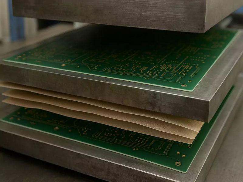
Plating Thickness in Press-Fit Holes
Press-fit demands more copper in the barrel than a conventional soldered hole, because the pin expands and contracts against the wall with every insertion. Typical requirements call for a minimum of 25 micrometres of copper, with some designs asking for more. Tin or tin-lead plating over the copper is common to improve the cold weld and protect the barrel.
Plating uniformity matters more than the average. A barrel that is thick at the entry and thin at the bottom corner will fail where the pin applies the greatest load, which is usually the lower half of the hole. Specify minimum thickness at the inner layers and at the bottom corner, and ask for section data rather than a surface reading.
Insertion Force, Tooling and Support
Insertion force is the measurable outcome of hole size, plating, pin design, and lubrication. Every connector has a recommended range, and a machine or press is set to apply force through a flat tool that bears on the connector body rather than on individual pins. Force that is too low leaves an unreliable connection, while excessive force buckles pins or drives them too deep.
Support is essential for a large backplane. The press must back up the board directly beneath the connector so that the insertion load passes through the tool, the connector, the board, and the support with minimal deflection. Without proper backing, the panel flexes, the pins nearest the support take more load than the rest, and the holes distort.
Laminate Selection and Pad Geometry
The laminate must resist the insertion load and the thermal cycles that follow. High glass transition materials with good dimensional stability are preferred, and thick backplanes benefit from rigid constructions that keep the hole geometry predictable. A soft resin can allow the barrel to deform under load and lose contact pressure over time.
Pad geometry contributes as well. A generous annular ring distributes the stress around the hole and prevents the pad from lifting when the pin expands. Inner-layer connections should be balanced so the load is not concentrated on one side. Where a design allows, spreading press-fit holes away from tight arrays improves thermal and mechanical behaviour.

Inspection, Rework and Repair Limits
Visual inspection confirms that each connector is seated squarely, at the right height, and without cracked or bent pins. Electrical test verifies continuity and isolation, and a resistance check on a sample of contacts can detect a marginal connection before it becomes a field failure. Because the joint is inside the hole, destructive verification is limited to coupons.
Rework is possible but limited. A connector can usually be extracted with a proper tool and replaced, but the hole and plating see additional stress with every cycle. Most specifications allow only one or two insertion cycles per hole, and the number should be tracked. Reusing a pressed connector is generally prohibited because the compliant section has already yielded.
Reliability Testing and Thermal Cycling
Press-fit connections are qualified by thermal cycling, vibration, and mechanical shock, with resistance monitored throughout. The connection typically improves slightly during the first cycles as the metal surfaces settle, then remains stable. A rising trend indicates that contact pressure is being lost, often because plating cracked or the barrel deformed.
Testing should use production-representative holes, plating, and pins, with coupons processed alongside the panels. Different pin designs behave differently, so a qualification that applies to one connector family does not automatically transfer. Keep the test conditions and results with the product record so that a design change can be assessed against a known baseline.
Process Control and Documentation
Control begins with the drill and plating processes that define the finished hole. Track hole size on coupons, monitor plating thickness by section, and verify insertion force on a sample from each lot. Log the press setup, the tooling used, and the operator, because insertion faults are often traced to a change in setup rather than to the boards.
Documentation should tie each of those measurements to the specification the customer approved. When a connector supplier issues an updated drawing with a new hole range, the drill and plating specifications must be rechecked before the next build. In press-fit work the tolerances are small enough that a small change in one document can invalidate the whole process.
FAQ
Can press-fit connectors be installed by hand? Small connectors can be seated with a hand tool, but production volumes use a controlled press with a flat insertion tool and proper backing. Hand insertion makes force difficult to control and often results in partially seated or damaged pins, which are hard to detect afterwards.
How many times can a press-fit hole be used? Most specifications allow one or two insertion cycles, with replacement connectors counted separately. Each cycle expands the barrel further and reduces the contact force available, so a hole that has seen multiple insertions should be evaluated rather than reused without question.
Why does hole plating thickness matter so much? The pin bears against the plated copper and relies on a gas-tight metallic contact. Thin plating cracks under the expansion load, exposing the laminate and increasing resistance, while uniform thick plating distributes the stress and keeps the connection stable through thermal cycling.