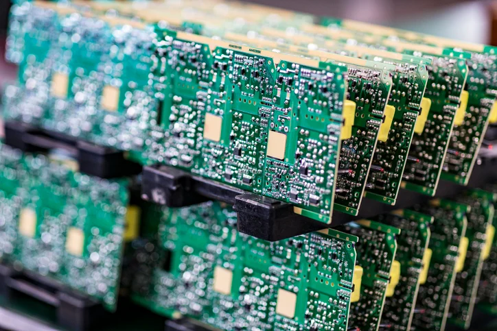
Thermal Via Array Design Under Power Devices
A power device mounted on a copper pad dissipates most of its heat through the board. The vias under the pad are the path, and their number, size and arrangement decide the junction temperature more than the pad area does.
The Path Through the Board
The heat leaves the device, spreads laterally into the copper, and then transfers through the dielectric into the layers below. The dielectric is the bottleneck, and the vias are the low resistance path through it.
Without vias the spreading is limited to a thin layer of copper, and the pad becomes a hot plate. With vias the heat reaches the inner planes and the far side. Our thermal notes describe the path calculation.
Via Geometry
A larger via carries more heat per via and takes more area. A smaller via can be placed in greater numbers and it is limited by the plating thickness in the barrel, which is where the thermal resistance is concentrated.
The plating thickness matters more than the diameter for the thermal resistance, because the heat has to pass through the barrel wall rather than through the hole. Our plating notes describe how the wall thickness is verified.
Placement Under the Pad
The vias should be placed where the heat is generated rather than spread evenly across the pad. Under a power device the source is a small area, so a dense cluster under that area performs better than an even distribution.
Vias placed at the edge of the pad contribute less, because the heat has to travel laterally before it reaches them. Our copper notes describe the spreading that happens before the vias.

Processing Constraints
Vias in a pad must be capped, plugged or filled, or the paste wicks into them during reflow and the joint is starved. The choice decides the surface the stencil seals on. Our via fill notes describe the options and their limits.
The via arrangement also affects the paste print. A large cluster of open vias under a pad produces a deposit that collapses into the holes, which is the case that forces a fill.
Effect on Soldering
The copper under a pad connected to a plane conducts heat away during reflow, so the joint forms later than its neighbours. The thermal relief or the plane connection has to be designed with the reflow in mind as well as the thermal performance.
The two requirements pull in opposite directions, and the compromise should be made deliberately. Our thermal mass notes describe the effect on the profile.
Thermal Cycling
A via in a pad is loaded by the expansion of the copper and the laminate, and the barrel can crack at the pad interface. The failure appears as a rise in thermal resistance rather than as an open, so it is found by measurement.
The arrangement should avoid a single large via where several small ones would do, because the load per via falls with the number. Our microvia notes describe the same mechanism at a smaller scale.
Verification
The verification is a temperature measurement on the real assembly at the worst case load, with a thermocouple on the device case and the board underside.
Where the measured temperature exceeds the calculation, the via plating thickness and the fill are the first items to check. Our quality notes describe how the result is recorded.
Process Control and Verification
On a design of this kind, spreading is the item that decides how the rest of the board is arranged. Where a value sits close to a process limit, the drawing should say so, since the shop can then open the process window rather than working to a nominal figure that carries no tolerance. A stack-up that is drawn rather than described removes most of the ambiguity from a quotation, and it lets the fabricator price the board against the dielectric and copper weights that will actually be used.
Where the requirement is not written down, the shop supplies its own default, and the default is chosen for the process rather than for the design. The measurements that matter are the repeatable ones: conductor width and spacing, annular ring, finished hole size, plating thickness and surface finish are all verifiable on a coupon that travels with the panel.
Running a first article through the same checks as the production panel confirms that the two agree, and that comparison is the cheapest form of process control available at prototype stage. Keeping a sample from the panel turns a dispute into a measurement, because the same coupon can be re-examined by both parties without rebuilding the batch.
Reviewing the design before the data is released is cheaper than correcting it after the panel is in the tank, because every step downstream inherits the decision made at the front end. Documenting the assumption is part of the design work, and a short note on the drawing prevents a question that would otherwise arrive a day later and cost a day of schedule.
Process Control and Verification
On a design of this kind, spreading is the item that decides how the rest of the board is arranged. Where a value sits close to a process limit, the drawing should say so, since the shop can then open the process window rather than working to a nominal figure that carries no tolerance. A stack-up that is drawn rather than described removes most of the ambiguity from a quotation, and it lets the fabricator price the board against the dielectric and copper weights that will actually be used.
Where the requirement is not written down, the shop supplies its own default, and the default is chosen for the process rather than for the design. The measurements that matter are the repeatable ones: conductor width and spacing, annular ring, finished hole size, plating thickness and surface finish are all verifiable on a coupon that travels with the panel.
Process Control and Verification
On a design of this kind, spreading is the item that decides how the rest of the board is arranged. Where a value sits close to a process limit, the drawing should say so, since the shop can then open the process window rather than working to a nominal figure that carries no tolerance. A stack-up that is drawn rather than described removes most of the ambiguity from a quotation, and it lets the fabricator price the board against the dielectric and copper weights that will actually be used.
Process Control and Verification
On a design of this kind, spreading is the item that decides how the rest of the board is arranged. Where a value sits close to a process limit, the drawing should say so, since the shop can then open the process window rather than working to a nominal figure that carries no tolerance. A stack-up that is drawn rather than described removes most of the ambiguity from a quotation, and it lets the fabricator price the board against the dielectric and copper weights that will actually be used.
A first article check confirms that the process and the drawing agree on the points listed above, and that the coupon data supports the values used in the design.

Where a measurement falls outside the expected window, the sample is retained so that the cause can be established before the balance of the batch is released.
FAQ
How many vias are enough? The number follows from the thermal resistance target, not from a count. The calculation should be done for the device and the plane arrangement.
Can unfilled vias be used in a thermal pad? They can, and the paste loss has to be accounted for in the aperture design. A filled and planarised pad gives a more predictable deposit.
What does gopcb provide for thermal via design? We provide thermal resistance targets translated into via count and geometry, clustering under the heat source, plating thickness verification, fill and planarisation selection for the paste, plane connection design that still reflows, and temperature measurement on the finished assembly.