Via Filling and Plugging: Tenting, Fill and Planarisation
A via does not have to be open. It can be covered, plugged or completely filled, and the choice is decided by what sits above the via and by what the via has to survive. The words are often used interchangeably, and that is where the specification goes wrong.
Why Fill a Via
An open via under a component pad wicks solder paste during reflow. The paste volume then falls below what the joint needs, and the result is a void or an open that appears with no obvious cause in the stencil or the profile.
A filled via also lets the surface be planar, which matters for a fine pitch area, for a press-fit zone and for any surface that must be smooth for a subsequent operation.
Tenting, Plugging and Filling
Tenting covers the via with solder mask. It stops the paste wicking and it costs nothing, but the mask can crack over the hole during thermal cycling and it leaves a dimple.
Plugging pushes material into the barrel without guaranteeing that it reaches the far side. Filling means the barrel and both ends are filled and the surface is planar. Only the third process gives a surface that can be placed on. Our hole types notes describe the classification.
Filling Materials
Epoxy is the common material because it is applied as a paste, cured, and then planarised by grinding. The cured plug must match the expansion of the board closely enough that it does not dome or shrink and pull the pad away.
Copper paste and plated fill are used where the thermal or current path through the via matters, because an epoxy plug is a poor conductor compared with the copper barrel it replaced.
The Process
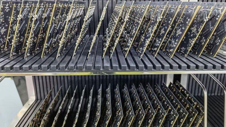
The board is filled from one side, the material is cured, and the excess is removed by grinding or by a planarisation pass. The sequence matters: filling before the outer layers are finished leaves a different surface than filling after.
Vacuum assistance is used where the aspect ratio is high, because the paste will not otherwise reach the bottom of a narrow barrel. A partially filled barrel looks acceptable from the top and is discovered only by cross section.
Via in Pad and HDI
Via in pad is the case that forces the decision. The via is inside a component pad, so the absence of a fill is a joint defect waiting to happen, and the fill must be flat enough for the stencil to seal on it. Our HDI via notes describe how the microvia levels interact with the fill.
The stencil aperture over a filled via should be sized for the remaining volume, and the printing parameters should be verified with a paste inspection step rather than assumed.
Voids and Reliability
A fill that contains voids reduces the thermal path and gives the plating a place to crack when the board flexes. The void content should be specified and measured on a coupon rather than judged from a photograph.
Thermal cycling is the test that exposes the difference between a good fill and an acceptable looking one, because the plug and the laminate expand at different rates. Our plating notes cover the barrel condition that the plug must protect.
Specifying the Requirement
The drawing should say which vias are tented, which are plugged and which are filled and planarised, and it should say whether the fill must be conductive. A general note that all vias are tented will be read literally and applied to the one via that mattered.
Where the fill is invisible after assembly, the verification has to happen at the board level, which means the specification must reach the fabricator before the order rather than after the first failure. Our fabrication notes notes list the attributes that should be stated.
Additional Considerations for This Build
Practical attention to via filling pays for itself here, because it decides whether the finished board behaves as the drawing intended. Where the requirement is not stated on the fabrication drawing or in the assembly notes, the shop has to assume a default, and that default is rarely the value the design was simulated with. Stating via filling explicitly, together with the tolerance that applies, removes the assumption and keeps the result predictable from batch to batch.
Process Control and Verification
On a design of this kind, via filling is the item that decides how the rest of the board is arranged. A stack-up that is drawn rather than described removes most of the ambiguity from a quotation, and it lets the fabricator price the board against the dielectric and copper weights that will actually be used. Where the requirement is not written down, the shop supplies its own default, and the default is chosen for the process rather than for the design.
The measurements that matter are the repeatable ones: conductor width and spacing, annular ring, finished hole size, plating thickness and surface finish are all verifiable on a coupon that travels with the panel. Running a first article through the same checks as the production panel confirms that the two agree, and that comparison is the cheapest form of process control available at prototype stage.
Keeping a sample from the panel turns a dispute into a measurement, because the same coupon can be re-examined by both parties without rebuilding the batch. Reviewing the design before the data is released is cheaper than correcting it after the panel is in the tank, because every step downstream inherits the decision made at the front end.
Documenting the assumption is part of the design work, and a short note on the drawing prevents a question that would otherwise arrive a day later and cost a day of schedule.
Process Control and Verification
On a design of this kind, via filling is the item that decides how the rest of the board is arranged. A stack-up that is drawn rather than described removes most of the ambiguity from a quotation, and it lets the fabricator price the board against the dielectric and copper weights that will actually be used. Where the requirement is not written down, the shop supplies its own default, and the default is chosen for the process rather than for the design.
Process Control and Verification
On a design of this kind, via filling is the item that decides how the rest of the board is arranged. A stack-up that is drawn rather than described removes most of the ambiguity from a quotation, and it lets the fabricator price the board against the dielectric and copper weights that will actually be used. Where the requirement is not written down, the shop supplies its own default, and the default is chosen for the process rather than for the design.
A first article check confirms that the process and the drawing agree on the points listed above, and that the coupon data supports the values used in the design.

Where a measurement falls outside the expected window, the sample is retained so that the cause can be established before the balance of the batch is released.
FAQ
Is tenting enough for a via in a pad? No. Tenting leaves a dimple and the mask can crack, and neither is acceptable under a pad that has to be printed and reflowed.
Does a filled via conduct heat as well as an open one? Only if the fill is copper based. An epoxy plug is a thermal barrier, and a design that relies on the via for heat must say so and use a conductive fill.
What does gopcb provide for via fill? We provide via classification on the drawing, fill and planarisation with cure control, vacuum assistance for high aspect ratio barrels, void measurement on a coupon, paste volume verification over via in pad, and cross section checks that confirm the barrel is filled.