Poka Yoke: Design Rules and Process Limits
A mistake proofing feature is one that makes an error impossible or immediately obvious rather than relying on the operator to notice it. In electronics assembly the errors that matter most are the ones that produce a working product at the factory and a failure later: a connector inserted the wrong way, a board installed upside down, a cable plugged into the wrong socket, a fastener omitted. Poka yoke is the practice of designing those errors out.
This article explains what mistake proofing means in a board design, which features are worth including, and how the effect is measured.
What Mistake Proofing Means
The principle is that an error is caught at the moment it is made rather than at the next inspection. The mechanism may be physical, such as a key that only fits one way; it may be visual, such as a marking that makes a wrong orientation obvious; or it may be a process step that cannot proceed until the previous one is confirmed. The first of those is the strongest, because it does not depend on anyone noticing.
On a printed circuit board the design features that provide the first kind are limited, since the board is a passive object. The strong features are usually at the interface: a connector that only mates one way, a mounting pattern that only fits one orientation, a pin header whose row spacing prevents a wrong insertion. The rest of the effort goes into making the correct state visible. Related placement decisions are described under placement order and pad positioning.
Design Features That Prevent Errors
An asymmetric outline prevents a board from being mounted upside down or back to front, and it costs nothing beyond a decision at the outline stage. An asymmetric mounting hole pattern does the same for a board that is fixed with several screws, and it is more robust than a silkscreen arrow because the assembly physically cannot be completed incorrectly.
A connector that has a mechanical key, or a housing that is polarised so that only one orientation mates, prevents the error at the cable rather than at the board. Where a set of connectors of the same type is used for different signals, the strongest measure is to use different sizes or different keying for each, so that a cable can only reach the socket it belongs to. The mechanical arrangement of the outline and the fixings is described under board outline and mounting design.
Visual And Legend Features
Where a physical barrier is impossible, the next best measure is a marking that is unambiguous and readable at the moment of assembly. A polarity mark beside a diode, a pin one indicator on a connector, a revision letter and a part number on the board and a clear legend for the test points all reduce the chance of an error and, more importantly, increase the chance that an error is noticed.
The mark has to survive the assembly process and remain readable. A marking under a component, on a surface that will be coated, or in a font too small to read is a mark that does not function. The rules for text size and placement are given in the silkscreen discussion under manufacturable design guidelines.
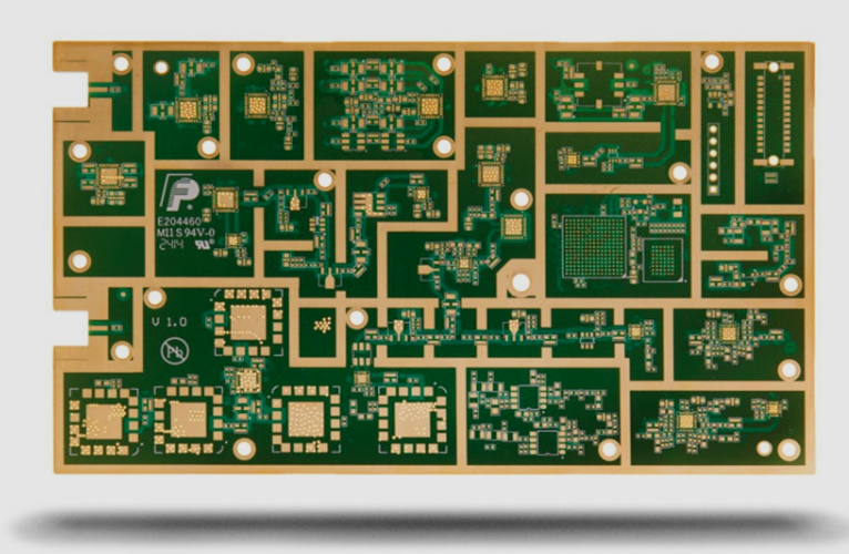
Mistake Proofing In The Assembly Process
Most of the practical measures are in the process rather than in the board. A fixture that only accepts the board in the correct orientation, a feeder setup that is verified against the program, a first article inspection that is performed before the lot continues and a test that fails the unit if a connector is inserted the wrong way are all mistake proofing. None of them is a board feature, and all of them depend on the board design for the ability to work.
The strongest process measure is the one that cannot be defeated. A test fixture whose connector is keyed so that the unit cannot be plugged in the wrong way, and whose program therefore cannot run on a wrong board, is a poka yoke. A test that requires the operator to confirm an orientation is not, because it depends on the operator. The assembly sequence that these steps belong to is described under PCBA development process.
Limits And Cost
A mistake proofing feature costs something. An asymmetric outline uses board area, a set of different connectors is more expensive than a set of identical ones, and a keyed fixture costs more to build. The cost has to be weighed against the cost of the error, which is the cost of the rework plus the cost of the ones that escape.
The judgment is different for a prototype and for a product. A prototype is built once and inspected carefully, so the effort belongs elsewhere. A product that will be built in thousands, by different operators, over years, justifies a great deal of design effort to remove an error that would otherwise happen regularly. The useful question is not whether the feature is worth it, but how often the error would occur without it and what it would cost each time.
Measuring The Effect
The effect is measured by the defect rate by type, tracked over time and compared before and after the change. A defect that disappears when a keying feature is added can be attributed, and the same data justifies the next measure. A defect rate that does not change indicates that the assumed cause was not the real one, which is itself useful information.
The other measurement is the escape rate, which is the number of defects that reach the customer rather than being caught. A mistake proofing feature that moves a defect from the escape category to the caught category has improved the process, while one that only makes the defect easier to find has not. The two figures together describe whether the measure worked. The process control that supports them is described under PCBA development process.
Where Errors Actually Happen
Mistake proofing is most valuable where the error is easy to make and hard to detect. The classic cases in electronics are a connector of the same family used for two different signals, a mounting pattern that is nearly symmetric, a fuse or a jumper that can be fitted in two positions, a battery holder that can be loaded either way and a set of screws of two lengths that both fit the same hole. Each of those produces a product that passes the build and fails later or, worse, passes the test and fails in the field.
The second group is the errors that happen during service rather than during the build. A cable that can be plugged into the wrong socket, a module that can be inserted backwards or a board that can be replaced with the wrong revision all belong to the same family. Designing for the service technician rather than only for the production line is what makes the second group preventable, and it costs the same as designing for the first.
FAQ
Is a silkscreen mark a poka yoke? It is a weak one, because it depends on the operator noticing it. It is useful, and a physical feature that prevents the error is stronger.
Can software be used for mistake proofing? It can, where the product has a processor. A firmware that detects a wrongly connected input and refuses to start is a mistake proofing measure, and it requires the hardware to make the incorrect state detectable.
Does mistake proofing replace inspection? No. It removes specific errors, and inspection remains necessary for the errors that have not been designed out. The two are complementary, and the design effort is best spent on the errors that inspection catches least reliably.