ACF And Hot Bar Bonding For Flex Connections
A hot bar bonding machine joins a flex tail to a rigid board by pressing a heated blade onto the joint while the adhesive between the two parts cures. Where the connection is made with anisotropic conductive film, the film carries current only in the direction of the compression, so hundreds of conductors can be joined in one operation without any risk of bridging between them.
This article covers how the joint is built, how the film conducts, how force and temperature are set, and how the result is inspected.
How The Joint Is Built
The rigid board carries a row of pads, and the flex tail carries a matching row. The film is placed over the pads, the tail is aligned on top, and the assembly is tacked so that it cannot move. The hot bar then descends, presses the row of conductors together and holds them at temperature while the adhesive matrix softens, flows around the particles and cures. On cooling, the cured adhesive holds the parts in compression and the particles provide the electrical path.
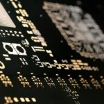
Everything depends on alignment and on the planarity of the two parts. A tail that is offset by a fraction of a pad pitch leaves a conductor partly over the pad and partly over the gap, which raises the resistance of that line and lowers the adhesion at the edge. A rigid board that is not flat, or a flex tail with a stiffener that is thicker at one end, produces a pressure gradient along the row, so one end of the joint is compressed and the other is not. Where access is limited, the pads themselves are often designed with the conventions described under PCB pad design standards.
How Anisotropic Film Conducts
The film is an adhesive loaded with conductive particles, typically a few micrometres across, at a loading low enough that the particles do not touch each other in the plane of the film. When the film is compressed between a pad on the board and a conductor on the flex, the particles are trapped between the two surfaces and form a conducting bridge through the thickness. In the plane of the film, the particles remain separated by adhesive, so neighbouring conductors stay isolated.
That mechanism sets the requirements. The number of particles captured under each conductor determines the contact resistance and its repeatability, so the particle density, the pad area and the compression all matter. Pads that are too small capture too few particles and give a joint with a high and variable resistance. Pads that are very large capture many particles but require more force to bring the whole area into contact. The pitch between conductors is limited by the film thickness and the particle size, because particles must not be able to bridge sideways when the film flows during bonding.
Bond Force And Temperature
Three parameters are set on the machine: the temperature of the blade, the force applied through it and the time the force is held. The temperature has to be high enough to cure the adhesive within the hold time and low enough that the flex substrate and the board laminate are not damaged. The force has to be high enough to capture enough particles and to squeeze the adhesive out of the contact area, and low enough that the conductors are not deformed or the film squeezed so thin that it fails mechanically.
The force is applied through a blade whose width is a fraction of the joint length, so the joint is bonded in several steps as the blade indexes along it. Each step must apply the same pressure, and the overlap between steps must be enough that every point receives the full cure. Where a joint is long, this indexing is the dominant part of the cycle time, and a blade that is too narrow makes the process slow while a blade that is too wide fails to follow the contour of the parts. The alignment of the two parts before bonding follows the same principles as in placement order and pad positioning.
Curing And The Cured Joint
The cured joint is held together by the adhesive, not by a metallurgical bond, so its strength depends on the cure and on the adhesion of the film to both surfaces. An under-cured joint still conducts when it is made and loses contact later as the adhesive creeps. An over-cured joint becomes brittle and cracks at the edge of the bonded region when the flex is moved. The cure window is narrow, which is why the blade temperature and the hold time are controlled and recorded rather than set by feel.
The surfaces also have to be clean. A flux residue, a mould release agent or a fingerprint on the pads reduces adhesion and, worse, can leave a film between the particle and the pad that raises the contact resistance. Where the pads have been touched during assembly, the joint should be cleaned before bonding, and the film should be handled with tools rather than fingers. The cleanliness requirements are the same in principle as those described under design guidelines for manufacturability.

Inspection And Rework
The joint is inspected for alignment, for the presence of the film along the row and for the appearance of the fillet, and it is tested electrically by measuring the resistance of each conductor. A four wire measurement is preferred where the resistance matters, because it removes the resistance of the probes from the result. A joint that looks correct and measures a resistance several times higher than its neighbours has captured too few particles, and it will drift further with thermal cycling.
Rework is difficult and should be assumed to be a limited option. The film can be softened with heat and the tail lifted, but the pads must then be cleaned completely and the process repeated, and the second bond is usually weaker than the first because the surfaces have been disturbed. A bond that fails is often treated as a scrapped assembly rather than a repairable one, and the design should provide a test point that makes the failure visible before the product is assembled. The quality measures that apply to such a joint are described under the quality characteristics of a board design.
Where The Process Is Heading
Bonding is moving toward finer pitches and shorter cycles at the same time. Films that cure faster allow a lower blade temperature and a shorter hold, which reduces the thermal load on the flex, and finer particles allow a narrower conductor pitch without the risk of sideways bridging. Both changes demand tighter control of the bond force, because a thinner film with smaller particles has less tolerance for a pressure gradient along the row.
The practical limit is usually the board rather than the film. The pads must be flat and clean, and their positional tolerance across the row has to be small compared with the pitch. Where the laminate moves between the time the pads are etched and the time the bond is made, the alignment budget is spent before the machine is set, and the fix then belongs in the fabrication process rather than in the bonding parameters.
FAQ
Why not solder a flex tail instead? Soldering works where the pitch is coarse and the substrate can take the temperature. At fine pitch, the risk of bridging and the thermal load on the flex make a hot bar bond with anisotropic film the more controllable option.
Does the joint carry current through the adhesive? No. Conduction is through the particles trapped between pad and conductor, and the adhesive provides the mechanical strength and the insulation between adjacent conductors.
What causes a joint to fail after a thermal cycle? Usually an under-cured adhesive, which creeps and lets the compression fall, or a contaminated pad, which leaves a resistive layer under the particles. Both show up as a resistance that rises with temperature cycling rather than a joint that opens suddenly.