Through-hole PCB assembly is a proven electronic manufacturing technology in which component leads are inserted through drilled holes in a printed circuit board (PCB) and soldered to copper pads. Although surface mount technology (SMT) has become the dominant assembly method for compact and high-density electronics, through-hole technology (THT) remains an important solution for applications requiring strong mechanical connections, high component durability, and reliable performance under demanding operating conditions.
Unlike SMT components, which are soldered directly onto surface pads, through-hole components extend through the PCB. This structure creates a mechanically robust connection that is particularly valuable for connectors, transformers, power components, large capacitors, switches, relays, and other components exposed to mechanical stress.
As an experienced PCB assembly manufacturer, Kingda provides comprehensive through-hole PCB assembly, SMT assembly, and mixed-technology PCBA solutions. Our manufacturing capabilities support customers throughout the product lifecycle, from PCB prototype manufacturing and engineering verification to small-batch production and volume manufacturing.
What Is Through-Hole PCB Assembly?
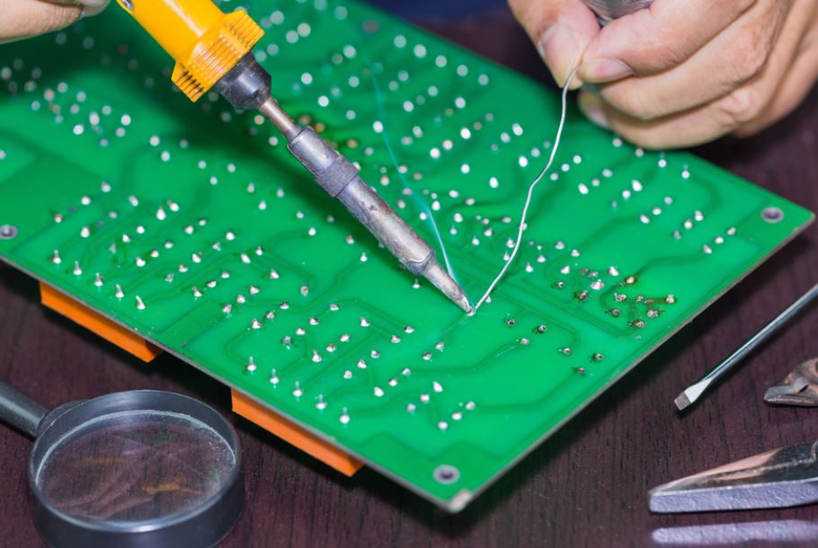
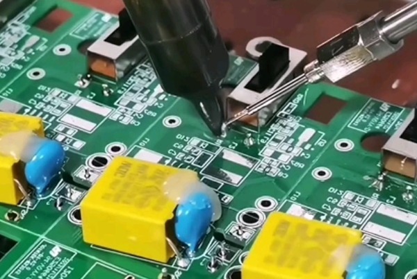
Through-hole PCB assembly is a PCB manufacturing process in which electronic components with wire leads are inserted into pre-drilled through-holes on a PCB. After insertion, the leads are soldered to copper pads, creating both an electrical connection and a strong mechanical attachment.
The basic THT PCB assembly process includes:
- PCB design and through-hole drilling
- Component preparation and insertion
- Component placement verification
- Wave, selective, or manual soldering
- Cleaning when required
- AOI and visual inspection
- Electrical and functional testing
- Final inspection and packaging
Through-hole assembly can be performed manually or through automated equipment. Manual through-hole assembly is commonly used for prototypes, repair work, and low-volume production, while automated insertion and soldering systems are more suitable for repeatable medium- and high-volume manufacturing.
Compared with SMT, THT generally requires more PCB area because each component needs a drilled hole and sufficient clearance for routing and assembly. However, the resulting mechanical strength makes THT particularly valuable for applications where reliability is more important than maximum component density.
What Is THT in PCB Assembly?
THT, or Through-Hole Technology, refers to the component-mounting technology used in through-hole PCB assembly.
The component leads extend through holes in the PCB and are soldered to pads on the opposite side. Depending on the component type and production requirements, the soldering process may use wave soldering, selective soldering, or manual soldering.
Common THT components include:
- Connectors
- Terminal blocks
- Transformers
- Relays
- Large capacitors
- Power resistors
- Switches
- Inductors
- Large heat sinks
- Certain diodes and transistors
THT is particularly useful when components must withstand repeated insertion forces, vibration, shock, thermal cycling, or mechanical loading.
Types of Through-Hole Components
Through-hole components are generally categorized according to the direction and arrangement of their leads.
Axial THT Components
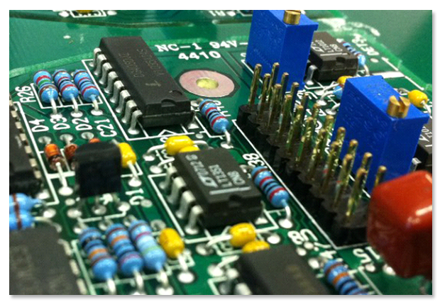
Axial components have leads extending from opposite ends of the component body. They are normally installed horizontally on the PCB.
Typical examples include:
- Axial resistors
- Certain diodes
- Some inductors
Their horizontal structure makes them suitable for automated insertion as well as manual assembly.
Radial THT Components
Radial components have their leads extending from the same side of the component body. They can generally be installed vertically or horizontally depending on the PCB design.
Common examples include:
- Electrolytic capacitors
- Some inductors
- LEDs
- Certain power components
Radial components are widely used in power electronics, industrial controls, consumer electronics, and other applications.
Through-Hole PCB Assembly Process
A reliable through-hole PCB assembly process requires careful coordination between engineering, component sourcing, PCB fabrication, assembly, inspection, and testing.
1. Engineering Data Verification
Before production begins, Kingda reviews the complete manufacturing data package to ensure that the PCB and components can be assembled correctly.
Typical documentation includes:
- Gerber or ODB++ files
- Bill of Materials (BOM)
- Schematic files
- Assembly drawings
- Component specifications
- Pick-and-place data when applicable
- Drill files
- PCB fabrication specifications
- Special inspection and testing requirements
The engineering team checks component footprints, hole diameters, lead dimensions, component orientation, polarity, spacing, and other assembly requirements.
A thorough DFM and DFA review can identify potential manufacturing problems before production begins, helping reduce rework, delays, and material waste.
2. PCB Drilling and Hole Preparation
Because THT components require leads to pass through the PCB, accurate through-hole drilling is essential.
The hole diameter must provide enough clearance for component insertion while maintaining an appropriate solder joint. Hole size, pad diameter, plating thickness, aspect ratio, and positional tolerance should all be considered during PCB design.
For multilayer boards, plated through-holes can also provide electrical connections between different copper layers.
3. Component Insertion
After the PCB is fabricated and inspected, THT components are inserted into the designated holes.
There are two primary approaches:
Manual insertion:
Operators install components according to the BOM, assembly drawings, and PCB silkscreen markings. This method is flexible and particularly useful for prototypes, repairs, engineering samples, and low-volume production.
Automatic insertion:
Automated insertion equipment places compatible axial or radial components at programmed positions. This approach improves consistency and production efficiency for repetitive manufacturing.
Before insertion, components should be verified for part number, value, orientation, polarity, and quantity to prevent assembly errors.
4. Component Soldering
After component insertion, the leads are soldered to the PCB pads.
Hand Soldering
Hand soldering uses a soldering iron and solder wire to create individual solder joints.
It is suitable for:
- PCB prototypes
- Low-volume production
- Engineering modifications
- Rework and repair
- Large or unusual components
- Components that cannot be processed automatically
Although flexible, manual soldering depends heavily on operator skill and process control.
Wave Soldering
Wave soldering is one of the most widely used automated methods for THT assembly.
The PCB passes over a controlled wave of molten solder. The solder contacts the exposed leads and pads on the underside of the board, creating multiple solder joints during a single pass.
A typical wave soldering process includes:
Flux application → Preheating → Solder wave → Cooling → Inspection
Process parameters such as flux quantity, preheat profile, solder temperature, conveyor speed, and wave height must be carefully controlled.
Selective Soldering
Selective soldering is especially useful for mixed-technology boards containing both SMT and THT components.
Instead of exposing the entire PCB to a solder wave, a programmable nozzle applies solder only to designated through-hole joints. This helps protect nearby SMT components and allows more precise thermal control.
For modern mixed SMT and THT PCB assembly, selective soldering can significantly improve process flexibility and reduce unnecessary thermal exposure.
Cleaning and PCB Assembly Inspection
After soldering, PCBAs may require cleaning depending on the flux chemistry, product requirements, and reliability specifications.
PCB Cleaning
Cleaning can remove:
- Flux residues
- Ionic contaminants
- Soldering residues
- Dust and other manufacturing contaminants
Depending on the process, manufacturers may use deionized (DI) water, aqueous cleaning systems, or qualified cleaning solvents.
However, not every assembly requires washing. No-clean flux processes may be appropriate when the selected materials and product requirements allow residues to remain on the board.
AOI Inspection
Automated Optical Inspection (AOI) uses cameras and image-processing algorithms to detect visible assembly defects.
Typical defects include:
- Missing components
- Incorrect component orientation
- Solder bridges
- Insufficient solder
- Excessive solder
- Component misalignment
- Lead-related defects
Visual Inspection
Experienced operators can perform visual inspection to identify defects that may require additional investigation or cannot be reliably detected by automated inspection alone.
Electrical Testing
Depending on product requirements, ICT, Flying Probe Testing (FPT), and Functional Testing (FCT) may be used to verify electrical performance.
Functional testing is particularly important because it evaluates whether the completed PCBA performs according to its intended operating specifications.
Advantages of Through-Hole PCB Assembly
1. Superior Mechanical Strength
One of the most important advantages of through-hole assembly is its mechanical robustness.
Because component leads pass through the PCB, the resulting solder connection provides stronger mechanical anchoring than a typical surface-mounted connection. This makes THT particularly suitable for components subjected to vibration, shock, mechanical loading, or repeated mating cycles.
Applications include:
- Industrial equipment
- Automotive electronics
- Aerospace systems
- Power supplies
- Communication equipment
- Industrial control systems
2. Excellent Reliability for High-Stress Applications
The mechanically reinforced structure of THT components makes them suitable for demanding operating environments.
When properly designed and processed, through-hole solder joints can provide reliable performance under mechanical and thermal stresses.
3. Suitable for Large and Heavy Components
Large components can be difficult to secure using SMT alone.
Through-hole mounting is often preferred for:
- Transformers
- Large connectors
- Relays
- Large capacitors
- Power inductors
- Terminal blocks
- High-power components
The leads passing through the PCB provide additional mechanical support.
4. Easier Prototyping and Repair
THT components are generally easier to handle manually than very small SMT packages.
This makes through-hole PCB assembly convenient for:
- Prototypes
- Engineering samples
- Low-volume production
- Troubleshooting
- Component replacement
- Repair and rework
5. Good Current-Carrying Capability
For certain component types and PCB designs, through-hole connections can accommodate relatively large terminals and substantial copper structures, making THT suitable for power-related applications.
However, actual current capacity depends on the complete electrical and thermal design, including conductor width, copper thickness, component construction, temperature rise, and cooling conditions.
Disadvantages of Through-Hole PCB Assembly
Despite its advantages, THT also has several limitations.
1. Lower Component Density
Because every THT component requires a drilled hole and sufficient clearance, through-hole assembly generally requires more PCB space than SMT.
This makes THT less suitable for highly miniaturized products where PCB real estate is limited.
2. Additional PCB Drilling
THT requires additional drilling operations and plated through-hole structures, which can increase PCB fabrication complexity and cost.
3. More Difficult High-Density Routing
Through-holes consume routing space and can interfere with signal routing on multilayer boards.
This can become particularly challenging in high-density designs involving:
- Fine-pitch components
- High-speed interfaces
- HDI structures
- RF circuits
- Dense multilayer PCBs
4. Lower Automation Flexibility for Certain Components
Not every THT component is compatible with automatic insertion equipment. Irregularly shaped, oversized, or unusual components may still require manual insertion.
5. Potentially Higher Assembly Cost
Compared with highly automated SMT production, THT assembly may require additional labor, drilling, component insertion, and soldering operations.
For this reason, many modern products use a combination of SMT and THT assembly rather than relying exclusively on either technology.
Through-Hole vs. SMT Assembly
| Characteristic | Through-Hole Technology (THT) | Surface Mount Technology (SMT) |
|---|---|---|
| Mechanical Strength | Excellent | Good |
| Component Density | Lower | Higher |
| Large Components | Excellent | Limited for some components |
| Miniature Components | Limited | Excellent |
| Automation | Good for compatible parts | Excellent |
| Prototyping | Convenient | Requires specialized equipment |
| Repairability | Generally easier | More challenging for fine-pitch packages |
| High-Density Routing | More challenging | More efficient |
| Power Components | Excellent for many applications | Excellent for suitable packages |
| High-Frequency Applications | Depends on design | Often advantageous |
| Production Volume | Low to high | Low to very high |
| Typical Applications | Connectors, power components, transformers, relays | ICs, resistors, capacitors, sensors, processors |
In many real-world products, mixed-technology PCB assembly provides the best solution.
SMT can handle small and high-density components, while THT provides additional mechanical strength for connectors, power components, and other mechanically stressed parts.
Common Through-Hole PCB Assembly Defects and Solutions
Incomplete Solder Fill
Possible causes:
- Incorrect preheat conditions
- Insufficient flux activation
- Incorrect solder temperature
- Inappropriate hole-to-lead clearance
- Excessive conveyor speed
- Poor PCB thermal balance
Solutions:
- Optimize the thermal profile
- Adjust flux application
- Verify hole and lead dimensions
- Optimize conveyor speed
- Improve PCB pad and thermal design
Solder Bridging
Possible causes:
- Excessive solder
- Incorrect wave parameters
- Poor component spacing
- Excessive flux
- Incorrect PCB orientation
Solutions:
- Optimize wave height and conveyor speed
- Adjust flux quantity
- Improve component spacing
- Optimize PCB design
- Apply selective soldering when appropriate
Component Misalignment
Possible causes:
- Incorrect insertion
- Component movement during soldering
- Excessive hole clearance
- Improper fixture design
Solutions:
- Improve insertion accuracy
- Use appropriate fixtures
- Verify component lead forming
- Perform first-article inspection
- Improve pre-soldering component retention
Insufficient Solder Joint Quality
Possible causes:
- Poor surface condition
- Inadequate flux
- Incorrect soldering temperature
- Contaminated PCB pads
Solutions:
- Strengthen incoming PCB inspection
- Optimize flux selection
- Control soldering parameters
- Improve material storage and handling
Heat Damage
Some THT components may be sensitive to excessive thermal exposure.
Solutions include:
- Optimize the soldering profile
- Use selective soldering
- Apply heat protection where appropriate
- Follow component manufacturer temperature specifications
- Use manual or localized soldering for sensitive components when necessary
Applications of Through-Hole PCB Assembly
Although SMT dominates many compact consumer electronics products, THT PCB assembly remains widely used in applications where mechanical strength, component size, or serviceability is important.
Typical applications include:
- Industrial control systems
- Automotive electronics
- Power supplies
- Aerospace and defense electronics
- Telecommunications equipment
- Medical equipment
- Instrumentation
- Motor control systems
- Energy equipment
- Audio amplifiers
- Industrial automation
- High-power electronic systems
For products exposed to vibration, shock, high current, or repeated mechanical loading, THT can provide significant design advantages.
Future Trends in Through-Hole PCB Assembly
Although SMT will continue to dominate high-density electronics manufacturing, through-hole technology is not disappearing. Instead, it is becoming increasingly integrated with modern automated manufacturing systems.
Selective Soldering
Selective soldering enables manufacturers to process THT components precisely while minimizing thermal exposure to nearby SMT components.
Automated Component Insertion
Modern insertion systems can improve consistency and productivity for compatible THT components.
Mixed SMT/THT Assembly
Combining SMT and THT enables designers to balance miniaturization, electrical performance, mechanical reliability, and manufacturing cost.
Advanced Inspection and Traceability
Automated inspection, electrical testing, barcode tracking, and manufacturing data management are improving process traceability and quality control across the entire PCBA production cycle.
DFM-Driven Design
Modern PCB manufacturers increasingly participate in the design stage through DFM/DFA engineering reviews, helping customers optimize component selection, hole dimensions, spacing, solderability, and assembly processes before production begins.
Why Choose Kingda for Through-Hole PCB Assembly?
As an experienced PCB manufacturer and PCB assembly service provider, Kingda offers integrated manufacturing support designed to help customers move efficiently from prototype development to production.
Professional THT and Mixed-Technology Assembly
Kingda supports through-hole assembly, SMT assembly, and mixed SMT/THT PCBA, allowing customers to select the appropriate technology according to component type, product structure, production volume, and reliability requirements.
Comprehensive PCB and PCBA Solutions
Rather than treating PCB fabrication and assembly as isolated processes, Kingda can support customers across the manufacturing chain, including:
PCB Design Review → DFM/DFA Engineering → PCB Prototype Manufacturing → Component Sourcing → SMT Assembly → THT Assembly → Inspection & Testing → Small-Batch Production → Volume Manufacturing
Engineering Support
Kingda’s engineering team can review manufacturing data before production, helping identify potential issues related to:
- Component footprints
- Through-hole dimensions
- PCB stack-up
- Component spacing
- Soldering requirements
- Assembly orientation
- Test requirements
- Manufacturability
Quality Control
Quality control is incorporated throughout the production process, from incoming material inspection and PCB fabrication through component placement, soldering, inspection, electrical testing, and final shipment.
Depending on the project, inspection and testing can include SPI, AOI, X-ray inspection, ICT, Flying Probe Testing, Functional Testing, and visual inspection.
Flexible Production Capability
Kingda provides manufacturing support for different production stages, including PCB prototypes, engineering samples, small-batch PCB assembly, and volume production.
This enables customers to maintain manufacturing continuity as their products move from initial design verification to commercial production.
Reliable Supply Chain Support
For turnkey projects, Kingda can assist with component sourcing and procurement, helping customers coordinate PCB fabrication, component supply, assembly, inspection, and delivery through a streamlined manufacturing process.
Conclusion
Through-hole PCB assembly remains an essential manufacturing technology despite the rapid development of SMT. Its strong mechanical connections, compatibility with large and heavy components, serviceability, and reliability make it particularly valuable for power electronics, industrial controls, connectors, automotive systems, aerospace equipment, and other demanding applications.
For modern products, the choice does not necessarily have to be THT vs. SMT. In many cases, the most effective approach is mixed-technology PCB assembly, using SMT for high-density and miniature components while using THT for components that require stronger mechanical support.
With professional engineering support, controlled soldering processes, comprehensive inspection, and reliable testing, Kingda provides through-hole PCB assembly and PCBA manufacturing solutions that help customers improve manufacturability, product reliability, and production efficiency—from PCB prototypes to volume manufacturing.