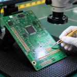
In multilayer PCB manufacturing, prepreg is an essential material used to bond copper layers and form the dielectric structure of the finished board. When optimizing a PCB Stackup, many projects face a difficult balance between electrical performance, material cost, manufacturing yield, and long-term reliability.
Two common approaches can create unnecessary risk. The first focuses primarily on electrical performance while paying insufficient attention to Prepreg Cost and material utilization. The second attempts to reduce material consumption aggressively by using thinner prepreg or lower resin content without sufficient process validation. Although the latter approach may reduce material costs initially, it can increase lamination defects, rework, scrap, and reliability risks.
A systematic PCB Prepreg evaluation process provides a more reliable way to optimize multilayer PCB structures. By evaluating material selection, stackup design, lamination performance, material consumption, and production yield throughout the product lifecycle, manufacturers can achieve a better balance between cost, electrical requirements, and manufacturing stability.

Problems Caused by Ignoring Prepreg Evaluation
In a conventional multilayer PCB development process, the hardware engineer completes the schematic, PCB layout, and stackup design before performing impedance simulation and releasing the manufacturing data.
Electrical requirements such as signal integrity, power distribution, and impedance may be thoroughly evaluated, while material consumption receives much less attention.
This can create several problems.
Excessive Prepreg Specifications
A stackup may use more prepreg sheets than necessary because material selection is based primarily on electrical requirements rather than manufacturing efficiency.
Multiple prepreg sheets may be stacked together to achieve a target dielectric thickness, even when a more efficient material combination could provide similar performance.
This increases material consumption and may also introduce additional variables into the lamination process.
Cutting and Layout Waste
Prepreg is typically supplied in standardized sheet or roll formats. The relationship between PCB panel dimensions and material dimensions can therefore have a direct impact on material utilization.
If panelization and prepreg cutting are considered separately, excessive offcut and unused material may occur.
The theoretical amount of prepreg required by the stackup is therefore not always equal to the actual material consumption.
Excessive Cost Reduction
The opposite problem occurs when engineers attempt to reduce Prepreg Cost simply by reducing dielectric thickness or resin content.
Insufficient resin may result in inadequate filling around inner-layer copper patterns. Depending on the board structure and material system, this can contribute to voids, poor bonding, resin starvation, dimensional variation, or delamination.
The cost of these manufacturing problems can easily exceed the material savings achieved by reducing prepreg consumption.
Therefore, prepreg optimization should focus on total manufacturing cost rather than material price alone.
Prepreg Evaluation During PCB Stackup Design
Prepreg evaluation should begin at the same time as PCB Stackup development rather than after the design has already been finalized.
A practical evaluation process can include the following steps.
1. Define Electrical and Reliability Requirements
Before selecting PCB Prepreg, establish the key requirements of the finished PCB, including:
- Target impedance and impedance tolerance
- Finished board thickness
- Copper thickness
- Number of layers
- Signal-layer structure
- Required dielectric spacing
- Operating temperature
- Humidity and environmental conditions
- Mechanical requirements
- Reliability requirements
- Surface finish and assembly process
For high-speed designs, dielectric constant and dissipation factor must also be considered at the relevant frequencies.
Material data should be evaluated using appropriate test methods and frequency conditions rather than relying on a single generic Dk value.
2. Review Standard Prepreg Materials
PCB manufacturers commonly maintain qualified material systems and standard prepreg constructions.
Where possible, designers should first evaluate materials that are already well characterized by the manufacturer.
This can reduce material complexity, simplify procurement, and improve manufacturing consistency.
However, using a standard material does not automatically mean that it is suitable for every stackup. Resin content, glass style, cured dielectric thickness, Dk/Df, copper pattern, and lamination conditions must still be evaluated.
3. Perform Impedance Simulation
The next step is to determine the required dielectric structure through impedance simulation.
For Impedance Control applications, the simulation should consider:
- Copper thickness
- Trace width
- Trace spacing
- Dielectric thickness
- Dielectric constant
- Signal-layer geometry
- Reference-plane configuration
- Finished copper geometry
Copper thickness should not be ignored. Plating and etching change the final conductor geometry, so the simulation model should reflect realistic finished dimensions.
The goal is not simply to obtain the nominal impedance value. The design should also have sufficient manufacturing margin.
4. Minimize Unnecessary Prepreg Combinations
Where the electrical and mechanical requirements allow it, designers can evaluate whether fewer prepreg sheets or more efficient material combinations can achieve the required dielectric structure.
However, fewer sheets are not automatically better.
The final selection should consider resin filling capability, glass styles, copper density, dielectric thickness, lamination behavior, and production repeatability.
A technically efficient stackup is one that minimizes unnecessary material complexity without compromising lamination quality or electrical performance.
5. Estimate Material Utilization
The preliminary Prepreg Cost assessment should include actual material utilization rather than only theoretical stackup consumption.
Important factors include:
- PCB panel dimensions
- Prepreg sheet or roll dimensions
- Cutting layout
- Number of panels per material sheet
- Material utilization rate
- Offcut percentage
- Scrap rate
- Production quantity
This allows engineers to compare different stackup options from a total-cost perspective.
Compare Multiple Stackup Options
A single stackup should not automatically become the production solution.
For projects with significant material costs or complex multilayer structures, two or three alternative stackups can be evaluated.
For example:
| Evaluation Factor | Stackup A | Stackup B | Stackup C |
|---|---|---|---|
| Impedance performance | Meets requirement | Meets requirement | Meets requirement |
| Prepreg quantity | Higher | Lower | Medium |
| Material complexity | Medium | Low | High |
| Lamination risk | Medium | Low/Medium | Medium |
| Material utilization | Medium | High | Medium |
| Production flexibility | Medium | High | Medium |
| Overall evaluation | Requires validation | Requires validation | Requires validation |
The purpose of this comparison is not simply to select the stackup with the lowest material cost. The final decision should consider electrical performance, material availability, Lamination Process, manufacturing yield, reliability, and total cost.
Prototype Stage: Validate Prepreg Consumption and Reliability
Once the stackup is selected, prototype production should validate both electrical and manufacturing performance.
Testing only whether the PCB functions electrically is not sufficient for a complete PCB Prepreg evaluation.
Track Actual Prepreg Consumption
The actual amount of prepreg used during prototype production should be compared with the theoretical estimate.
Differences may result from:
- Cutting losses
- Panel layout
- Production scrap
- Material handling
- Process adjustments
- Additional material requirements for specific structures
This data provides a useful baseline for future cost optimization.
Perform Microsection Analysis
Microsection analysis can help evaluate the internal structure of the multilayer PCB.
Depending on the application and quality plan, inspection may include:
- Resin filling around copper features
- Interlayer bonding
- Dielectric thickness
- Copper thickness
- Via structure
- Voids or delamination
- Registration between layers
For high-reliability boards, internal structural validation can reveal problems that may not be visible through electrical testing alone.
Verify Impedance at Multiple Locations
For impedance-controlled multilayer boards, testing should be performed according to the defined quality plan.
Measurements at different locations can help identify potential variations associated with:
- Dielectric thickness
- Copper distribution
- Lamination uniformity
- Material variation
- Etching variation
- Panel position
This is particularly important when the design has narrow impedance tolerances.
Perform Reliability Testing
Depending on the application, reliability validation may include:
- Thermal cycling
- Thermal shock
- Temperature-humidity exposure
- Moisture resistance
- Soldering heat resistance
- Interlayer bonding evaluation
The specific test conditions should be determined by the product’s requirements and applicable standards.
Do Not Solve Every Lamination Problem by Adding Prepreg
When a prototype shows lamination defects, simply increasing prepreg thickness is not always the correct solution.
A defect may result from several different factors, including:
- Insufficient resin filling
- Incorrect prepreg selection
- Excessive copper density
- Uneven copper distribution
- Lamination temperature
- Pressure profile
- Heating rate
- Vacuum conditions
- Material moisture
- Stackup construction
- Pressing equipment
Therefore, engineers should first identify the actual root cause.
For example, if the selected prepreg already provides sufficient resin filling but the lamination profile is not optimized, changing the material may increase Prepreg Cost without solving the underlying process problem.
Process optimization can sometimes improve yield without increasing material consumption.
Prepreg Change Control During Mass Production
After a product enters volume manufacturing, material and process changes can affect both material consumption and production stability.
Changes requiring evaluation may include:
- Prepreg supplier changes
- Prepreg model changes
- Glass-style changes
- Resin-content changes
- Core material changes
- Copper thickness changes
- Board thickness changes
- Lamination process changes
- Press equipment changes
A material that appears equivalent on paper may behave differently during lamination because its resin flow, curing characteristics, glass construction, or thermal properties differ.
Therefore, a change-control process should be established before production changes are implemented.
Revalidate Significant Material Changes
When a major PCB Stackup material changes, a controlled engineering build or small production run should be considered.
The evaluation can include:
- Actual material consumption
- Lamination quality
- Finished dielectric thickness
- Impedance performance
- Microsection inspection
- Board dimensions
- Reliability results
- Production yield
This provides objective data for determining whether the new material system is genuinely equivalent to the original solution.
Monitor PCB Yield and Material Consumption
Material cost optimization should be monitored together with PCB Yield.
A useful production dashboard can track:
- Theoretical prepreg consumption
- Actual prepreg consumption
- Material utilization
- Cutting waste
- Lamination scrap
- Overall PCB Yield
- Rework rate
- Delamination rate
- Impedance pass rate
- Material lot variation
If material consumption gradually increases, engineers should investigate the reason rather than simply accept the higher cost.
Potential causes include inefficient cutting layouts, changes in panelization, material substitutions, increased scrap, or additional prepreg requirements introduced during process adjustments.
Incoming Material Control
The quality of incoming prepreg has a direct influence on the stability of the Lamination Process.
Depending on the material and quality requirements, incoming inspection may verify relevant characteristics such as:
- Material identification
- Thickness
- Resin content
- Glass style
- Storage condition
- Lot information
- Manufacturer documentation
Material storage is also important. Prepreg should be handled according to the material manufacturer’s specified storage conditions and shelf-life requirements.
Moisture exposure, temperature fluctuations, and improper storage can affect processing behavior and should be controlled through established material-handling procedures.
A Practical Prepreg Cost Optimization Workflow
A systematic workflow can be organized into four stages.
Stage 1: Stackup Design
- Define electrical and reliability requirements
- Select suitable material systems
- Perform impedance simulation
- Evaluate dielectric thickness
- Compare multiple stackup options
- Estimate material utilization
Stage 2: Prototype Validation
- Record actual prepreg consumption
- Perform microsection analysis
- Verify dielectric thickness
- Conduct impedance testing
- Evaluate lamination quality
- Perform application-specific reliability testing
Stage 3: Production Optimization
- Compare theoretical and actual material usage
- Analyze cutting losses
- Monitor PCB Yield
- Optimize panelization
- Review lamination parameters
- Identify recurring manufacturing losses
Stage 4: Engineering Change Control
- Review material substitutions
- Validate supplier changes
- Reassess the PCB Stackup
- Conduct controlled production trials
- Compare yield and material consumption
- Approve changes only after verification
Common Mistakes in Prepreg Cost Optimization
| Mistake | Potential Consequence | Better Approach |
|---|---|---|
| Selecting prepreg only by price | Higher process risk | Evaluate total manufacturing cost |
| Reducing dielectric thickness without validation | Lamination or impedance problems | Perform simulation and prototype validation |
| Using too many prepreg sheets | Higher material consumption | Evaluate alternative constructions |
| Ignoring cutting loss | Actual cost exceeds estimate | Include material utilization in the analysis |
| Changing prepreg without qualification | Process instability | Conduct controlled material validation |
| Focusing only on nominal Dk | Impedance variation | Consider frequency, thickness, and process variation |
| Adding prepreg to solve every defect | Higher cost without root-cause correction | Investigate the complete lamination process |
| Ignoring production yield | Hidden manufacturing cost | Evaluate material cost and PCB Yield together |
Balancing Cost, Electrical Performance, and Manufacturing Yield
The purpose of prepreg optimization is not to minimize material consumption at any cost.
A practical optimization target should consider three major dimensions:
Cost + Electrical Performance + Manufacturing Yield
Reducing Prepreg Cost is meaningful only when the resulting stackup continues to meet electrical, mechanical, reliability, and manufacturing requirements.
For high-speed multilayer PCBs, Impedance Control may place strict requirements on dielectric thickness and material characteristics. For high-reliability products, the priority may shift toward lamination robustness and long-term interlayer reliability.
Therefore, the optimal PCB Prepreg solution is usually not the one with the lowest material consumption. It is the solution that achieves the required performance with appropriate manufacturing margin and predictable production cost.

Kingda’s Approach to Multilayer PCB Stackup Optimization
Kingda can support a production-oriented evaluation process for multilayer PCB projects, covering stackup development, material selection, impedance considerations, prototype validation, and manufacturing optimization.
A systematic approach helps connect material decisions with actual production conditions instead of evaluating prepreg only from a theoretical electrical perspective.
For projects involving complex multilayer structures, tight impedance requirements, or cost-sensitive volume production, engineers can evaluate alternative material and stackup configurations before the design is frozen. Prototype data can then be used to validate lamination performance, material utilization, and production stability before broader manufacturing deployment.
Conclusion
Optimizing prepreg consumption is not simply a matter of reducing the number or thickness of prepreg sheets. A successful optimization strategy must consider the interaction between PCB Stackup, material properties, impedance requirements, lamination behavior, material utilization, and PCB Yield.
The most effective approach is to establish a complete evaluation process from stackup design through prototype validation and mass-production change control.
By comparing multiple solutions, monitoring actual material consumption, validating lamination quality, controlling material changes, and analyzing production yield, manufacturers can reduce unnecessary prepreg consumption without sacrificing PCB performance or reliability.
For multilayer PCB manufacturing, a balanced PCB Prepreg strategy provides a more sustainable path to cost reduction, process stability, and long-term production consistency.