Aluminium PCB Thickness: Thermal and Mechanical Effects
An aluminium board is chosen when the heat cannot be removed any other way. The metal base replaces the structural role of the laminate and adds a thermal path that conducts heat away through the board itself, and it is the thickness of that base, together with the thin dielectric above it, that determines how well it works.
What an Aluminium Board Is
A metal core board is built on a solid metal plate rather than on a glass reinforced laminate. The metal is normally aluminium, chosen for its thermal conductivity relative to its weight and cost, though copper core boards exist for applications where the thermal requirement justifies the additional cost and mass.
The circuit is formed on a thin copper foil bonded to the metal through a thermally conductive but electrically insulating dielectric layer. Almost all such boards are single sided, because bonding a second circuit layer to the other face doubles the cost and is rarely necessary, though a double sided metal core construction is available.
The Layer Structure
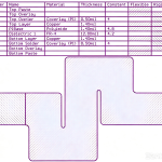
Three layers make up the stack: the circuit layer, which is the copper foil carrying the traces; the dielectric layer, which provides the electrical isolation; and the metal base, which provides the mechanical support and the thermal mass.
The dielectric is the critical layer. It has to be thin enough to conduct heat efficiently, thick enough to withstand the working voltage, and consistent enough that its thermal resistance is predictable. Typical thicknesses are between 60 and 150 micrometres, and the dielectric material is usually a filled epoxy or a polyimide with a ceramic filler to raise its conductivity.
Aluminium Base Thickness Options
The aluminium PCB thickness is usually quoted separately from the total board thickness, and the common values are 0.8 mm, 1.0 mm, 1.2 mm, 1.5 mm, 1.6 mm, 2.0 mm and 3.0 mm. A 1.6 mm base is the most widely used, because it gives a board that behaves mechanically like a conventional printed circuit board and fits standard handling equipment.
Thicker bases are used where the thermal mass or the mechanical stiffness is required, or where the board has to be mounted and used as a structural element. Thinner bases reduce weight and cost but give less heat spreading and less resistance to bending, so the choice is a balance between thermal performance and mechanical behaviour.
Thermal Resistance of the Stack
The thermal path from a component junction to the far side of the metal base has three components: the junction to the component case, the case through the solder and copper to the dielectric, and the dielectric itself. In most metal core boards the dielectric dominates, because it is the only electrically insulating layer and it is thin but has a much lower conductivity than the aluminium.
Increasing the aluminium thickness reduces the spreading resistance of the base but does little for the path immediately under the component. That is why the dielectric specification matters more than the base thickness for a concentrated heat source, while the base thickness matters for spreading heat across a larger area such as an LED strip or a power module.
<img src="https://www.gopcba.com/wp-content/uploads/2026/08/Automotive-PCB-Feature.webp" alt="Metal core PCB used as a heat spreading panel” />
Mechanical Strength and Flatness
Aluminium is stiffer than laminate of the same thickness, which is why a metal core board can be used as a structural panel in a product. It also does not absorb moisture, so it does not swell or delaminate, and it holds its flatness through thermal cycling far better than a laminate.
The other side of that coin is that aluminium expands about twice as much as laminate for the same temperature change, and far more than copper. In a single sided construction that is manageable, but the differential expansion stresses the dielectric and the solder joints when the assembly is thermally cycled. The component layout should avoid placing large rigid parts at the extremes of the board where the movement is greatest.
Interaction With Copper Thickness
The copper on an aluminium board is normally heavier than on a standard board, because the traces carry the currents that made the thermal solution necessary in the first place. Two ounce copper is common and up to six ounces appears on power boards, which raises the etch tolerance penalty in the same way as on any heavy copper design.
Heavier copper also improves the spreading of heat from the component footprint before it reaches the dielectric, which reduces the peak temperature at the centre of the pad and lowers the junction temperature of the device mounted on it. The interaction is worth modelling rather than estimating, since the combination of copper weight and dielectric thickness has more effect than either alone, and the current capacity side is covered in trace width and current calculation.
Manufacturing Limits
Metal core boards cannot be processed exactly like laminate. The metal base cannot be etched, so the circuit has to be formed on one side only, and the board cannot be drilled and plated through in the usual way. An electrical connection from the top side to the base is made either by a mechanical fastener or by a specially formed and press fit eyelet, since a plated through hole requires a dielectric barrel around the hole. The solder alloy used on the assembly also affects the joint behaviour on a metal base, as described in lead-free versus leaded solder.
Vias that cross the base are therefore unusual, and designs that need connections between layers of copper usually mount the components in a way that avoids it. The construction options are described in via in pad or plated through, and the assembly implications are the same as any single sided board with heavy copper.
Cost and Application Fit
A metal core board costs several times a comparable laminate board, driven by the aluminium, the filled dielectric, the single sided processing and the lower yield. It is therefore specified only when the thermal requirement cannot be met another way: LED lighting, power conversion modules, motor drives and high power amplifier stages are the classic applications.
In those applications the trade is straightforward. The metal base removes the need for a heat sink, a fan or a thermal interface on many designs, and it does so while providing mechanical structure at the same time. Where the dissipation is moderate, an ordinary board with copper pours and thermal vias is both cheaper and adequate, and the choice should follow a calculation rather than a preference.
FAQ
Does a thicker aluminium base mean a cooler component? Only if the heat is spread over a larger area. For a concentrated source the dielectric thickness and the copper spreading under the pad matter more, and increasing the base thickness alone may change very little.
Can a metal core board be double sided? It can, with a dielectric layer on both faces, but the cost rises sharply and the thermal benefit is limited. Most designs use a single layer and place the components that need cooling on that side.
Is aluminium better than copper for the base? Copper conducts heat about twice as well but is heavier and more expensive. Aluminium is the practical default, and copper is reserved for the most demanding thermal densities.