
Automotive PCBA Design: Assembly Spacing, Reflow, and Test Rules
Automotive assemblies are built to a stricter floor than consumer products, and most of that strictness lands on details that are decided during layout rather than during electrical design. Component spacing, reflow exposure, test access, and copper thickness all have to satisfy both the electrical requirement and a manufacturing process that will be audited. The rules below describe what an automotive PCBA design has to account for when the board moves from prototype to series production.
The underlying reason is service life. A vehicle module is expected to remain functional for ten to twelve years of vibration, thermal cycling, and humidity, so a joint that is merely acceptable at the end of assembly is not good enough. Each of the following rules exists because of a failure mode that appears in the field rather than on the test bench.
Component Qualification and Land Patterns
Every part on the bill of materials needs a specification that confirms it meets the automotive requirement for the location it will occupy, including whether an appropriate lead-free variant exists and whether its soldering profile is compatible with the process. If the datasheet cannot confirm it, the part should be replaced rather than qualified by assumption. Land patterns should follow the manufacturer recommendation rather than a generic library shape, because an undersized or oversized pad shifts the solder joint geometry and makes the assembly sensitive to placement tolerance.
For chip resistors and capacitors, slightly enlarging the pads beyond the nominal recommendation is a deliberate practice in automotive work. The larger joint absorbs more of the mechanical strain from vibration and thermal cycling, which reduces the risk of cracking at the fillet.
Component Spacing for Reflow and Rework
Component spacing is not aesthetic. Surface-mount parts should be separated by at least 0.4 mm measured across the outermost dimensions, which gives the convection flow room to heat each joint evenly. Mixed-technology assemblies need more room between through-hole and surface-mount parts, in the region of 3 mm, because the joints are made by different processes and rework has to be possible without disturbing neighbors.
Large and heavy components should be grouped so that they see only one reflow cycle, and tall parts should not be placed shoulder to shoulder, since they shade each other from the convection heat and create cold joints. Parts of the same type should be kept on the same side of the board wherever possible; splitting ten identical components across two sides complicates feeder setup and increases the risk of a placement error.
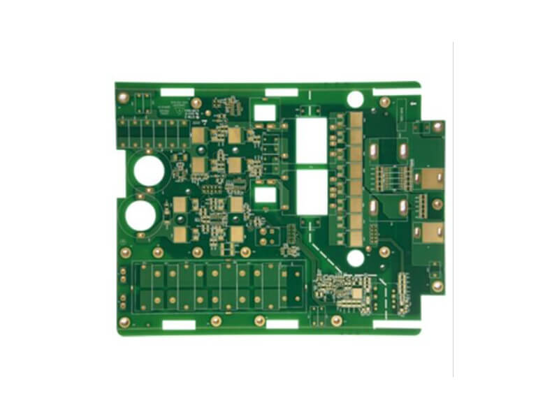
Polarized parts, including aluminum electrolytics, tantalum capacitors, and diodes, should be oriented consistently. Uniform orientation allows visual inspection to catch a reversed part before it reaches test, which is far cheaper than finding it after the module is assembled.
Placement Order and Double-Reflow Constraints
The number of reflow soldering exposures is a hard constraint, not a preference. Surface-mount aluminum electrolytic capacitors should be placed on the side that is reflowed only once, because a second exposure damages the seal and shortens the capacitor life. The same rule applies to large and heavy components: a part that is soldered twice can slump or detach during the second pass, producing a joint that passes inspection and fails later.
This is why the bottom side of a double-sided assembly carries the parts that can tolerate the additional thermal exposure, and why placement order matters early in the layout. Once the floorplan is set, changing which side a component sits on can force a substantial reroute. The mechanics of placement order are covered in placement order and pad positioning.
Process Edge, Test Point, and Panel Rules
Production tooling needs clear space at the edges of every board. Keep components at least 5 mm inside the process edge, and keep test points at least 3 mm inside it. Routing may pass through this band, but it should be covered with a protective coating so that the conveyor and the panel handling equipment cannot scratch the copper.
Provide a test point on every electrical net, and design the probe pad at approximately 0.99 mm diameter for in-circuit test access. Where the density makes that impossible for some nets, the decision about which nets to sacrifice should be made jointly by the electrical and layout engineers during design, and documented, rather than settled by whoever last edited the file.
V-scored panels need their own clearance: no components within 4 mm of the score line. Where an assembly requires adhesive or staking for mechanical support, that requirement has to be declared during layout so that a dispense area and a keep-out for the dispense nozzle are provided. Hand-soldering zones should be marked with a defined boundary so that operators and inspectors both know exactly which area is reworked by hand.
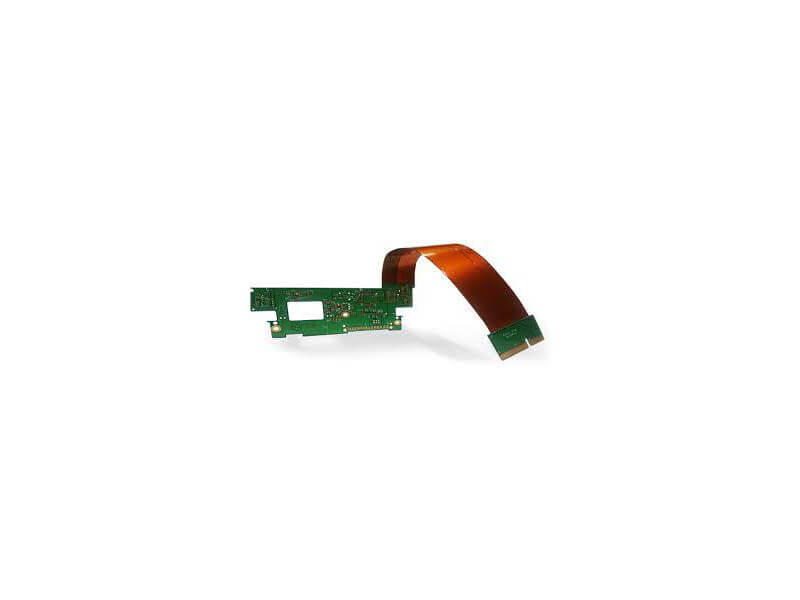
Connector selection belongs in the same review. A connector that is easy to insert but difficult to remove will be damaged during service, so insertion and extraction force should be considered part of the mechanical design rather than a purchasing decision.
Copper Thickness and Trace Width for Current
Automotive boards commonly use 35 micron (1 oz) finished copper, and the current-carrying rule of thumb in this design family is deliberately conservative: allow roughly 1 mm of trace width per ampere. That is a wider trace than a mild temperature rise calculation would require, and it exists because the ambient temperature inside a vehicle module is high and copper resistivity rises with temperature.
Set the minimum design width at 0.2 mm so the trace remains manufacturable after etch tolerance. Standard signal vias can be 0.4 mm, while vias that carry significant current should be 0.7 mm or larger, or better, several vias in parallel, since a single small via has far less copper cross-section than the trace feeding it. The full calculation method is described in trace width and current calculation.
Ground Partitioning for Audio and Display Sections
Mixed-signal automotive products need deliberate ground planning. For audio circuitry, a single-point connection to the main ground at the entry point is the usual approach: the radio and amplifier sections keep their own local ground, and the digital and analog grounds of the processor remain separate until that connection. Random vias placed to tie everything to the ground plane undermine the whole scheme, because they create return paths that carry digital current through the sensitive analog region.
Display sections have the same requirement between the driver IC’s digital and analog grounds. Poor partitioning shows up as visible image noise, which is not a functional failure but is a guaranteed customer complaint. High-voltage traces in the display area need their own spacing so that arcing cannot occur, and signal lines benefit from adjacent ground shielding.
ESD Protection and Board Level Immunity
Protection components only work if the disturbance reaches them before it reaches the circuit. Place the transient suppression device and its capacitor as close to the connector pin as the layout allows, with a short, direct path to the ground reference, because the impedance of the trace between the connector and the protector is what determines how much energy continues into the board. The same principle applies to filtering capacitors on the supply pins of every device: the closer they sit to the pin, the less effective series inductance stands between them and the transient. Placement errors of this kind are also a common cause of assembly defects, discussed in SMT component shift causes.
Mechanical and Thickness Requirements
Automotive boards are typically 1.5 mm or thicker, including small module boards, because the additional stiffness limits the flexure transferred to solder joints. On two-layer constructions, keep the minimum trace width at 0.2 mm, the minimum trace spacing at 0.25 mm, and the minimum copper pour gap at 0.3 mm. Where a mounting screw provides a ground connection, design the screw hole and the ground copper together so that the connection is solid; if the hole is not intended to carry ground, isolate it deliberately rather than leaving it connected by accident.
FAQ
Why enlarge chip component pads beyond the recommended land pattern? The larger joint has more solder volume and a longer fillet, which distributes the mechanical strain from vibration and thermal cycling over a greater area. In automotive service conditions this measurably reduces the incidence of fillet cracking compared with a minimum-size land.
Can a double-sided automotive assembly still be reliable? Yes, provided the second reflow is limited to components that tolerate it. Keep electrolytic capacitors and heavy parts on the single-reflow side, group identical parts on one side, and verify the profile on the second pass rather than assuming the first-pass profile still applies.
How many test points does an automotive board need? One per net is the target, with probe pads sized around 0.99 mm. If density forces a reduction, the nets that lose test access should be chosen deliberately, based on which ones can be verified functionally or by boundary scan, and the decision should be documented for the production test engineer.