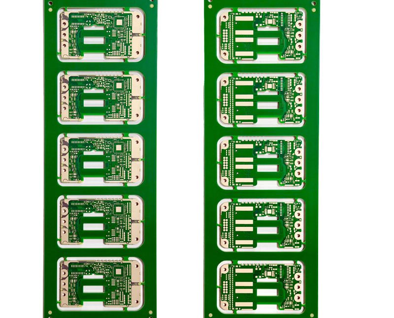
BGA Assembly versus LGA Assembly: Process and Inspection
BGA and LGA packages solve the same problem in two different ways. Both put a dense array of connections on the underside of the device so that hundreds or thousands of inputs and outputs fit under a chip the size of a thumbnail. The difference is what sits between the package and the board, and that difference propagates through the land pattern, the stencil, the reflow profile, the inspection method and the rework plan.
Same Array, Different Connection
A ball grid array carries a set of solder balls attached to the package. During reflow the balls and the printed paste coalesce into a joint, and the standoff between package and board is set by the ball diameter. The balls also act as a compliant layer that absorbs some of the mismatch between the package and the board as the assembly cools and as it heats in service.
A land grid array has flat metal pads on the package instead of balls. The joint is formed entirely from the solder paste printed on the board, so the standoff is much smaller, the solder paste volume becomes a critical process parameter, and the flatness of the package and of the board matter far more. The same array, a very different set of process sensitivities.
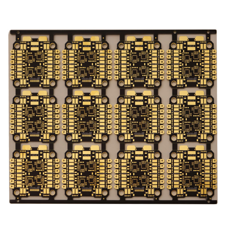
What BGA Assembly Involves
A BGA assembly flow begins with incoming inspection of the board and the device, then stencil printing, solder paste inspection, placement, reflow, and inspection by automated optical and X-ray methods. Fine pitch devices make each step tighter. Paste deposit volume has to be uniform across the array, the stencil aperture and the board pad must be matched, and the placement machine must have the accuracy and the optical capability to align the package to the pads on the board.
Reflow is where the joint is formed and where a poorly chosen profile shows up. The soak, the ramp and the peak must suit the paste, the board thickness and the thermal mass of the package, and the profile should be verified with a thermocouple on the actual assembly rather than taken from the paste datasheet. The general balance between alloys and profiles applies here too, and the trade offs are set out in lead free versus leaded solder.
What Changes with LGA Assembly
LGA assembly keeps the same sequence but moves the difficulty. Because there are no balls to supply material, coplanarity becomes the dominant concern: if the package or the board is warped, the centre of the array can lift away from the paste and produce open joints that the X-ray image shows only as a thin or missing deposit. Paste volume has to be enough to bridge the gap without bridging between adjacent pads.
The land pattern also has to be reproduced exactly from the device datasheet. A pad that is slightly too large draws solder away from the joint, and a pad that is too small leaves too little material to form a fillet. For both package types the starting point is the vendor recommended land pattern, and the fabricator should be given the pitch and the pad tolerance rather than left to infer them.
Land Pattern, Fanout and the Board
Routing out of a dense array is what drives the board technology. A dog bone fanout with a via beside each pad works down to a certain pitch; below that, vias must be placed inside the pads or on a finer grid, which brings the board into HDI territory. The number of layers and the via technology are decided by the escape routing, and the choice between via in pad and a conventional plated through via has consequences for the assembly step as well. The via structures available and what each one implies for the stackup are described in blind and buried via stack selection.
The trade offs between the options, including the need to fill or cap vias inside pads to avoid solder wicking away during reflow, are described in via in pad or plated through. Whichever route is chosen, the design should be checked for the smallest annular ring and the tightest trace and space that the fabricator can hold at volume, not just at prototype.
Inspection and What Each Method Can See
With both package types the joints are hidden, and the inspection strategy has to compensate. Solder paste inspection catches printing defects before they become joints. Automated optical inspection confirms placement, polarity and the visible portion of the joint around the perimeter. X-ray inspection sees through the package and reveals voids, bridging, insufficient material and the misalignment that optical methods cannot reach.
X-ray inspection is not equally informative for both types. A ball grid array produces a clear image of the balls and their collapse; an LGA joint is a thin layer with much less contrast, so the interpretation depends more on the operator and on the technique. That difference should be considered when a product requires a documented inspection record rather than a simple pass or fail.
Rework and Reliability
Rework of either package requires heating the whole device, removing it, cleaning the site and replacing it with a new part, because a device that has been removed cannot be reused. On a ball grid array the reballing step is normally avoided by using a new device; on a land grid array there is nothing to reball, but the site has to be restored to a flat surface with the right amount of paste. Both operations are feasible and both are best avoided.
Reliability follows the joint geometry. A taller joint with more material tolerates thermal cycling better, which favours the ball grid array in applications with large temperature swings, while the lower standoff of a land grid array produces lower inductance, which favours it in radio frequency and high speed applications where the electrical path matters more than the mechanical margin.
Cost and Selection
Cost is not decided by the package name. A fine pitch ball grid array may force an HDI board with microvias, via in pad and a controlled impedance stackup, and that board cost dominates the assembly cost. A land grid array on a modest pitch may sit on a standard multilayer board and cost less overall despite the tighter process window. The comparison only becomes meaningful when both are quoted from the same board, the same stackup and the same volume.
The practical selection rule is to start from the device and the routing that the device requires, then choose the board technology that the escape routing needs, and only then compare assembly cost. Choosing the package first and forcing the board to follow is how programmes end up with a stackup that is expensive for reasons nobody can explain.
FAQ
Is a BGA more reliable than an LGA? Not inherently. The taller ball joint tolerates thermal cycling better, while the flatter land connection has lower inductance. The application decides which property matters more.
Can both be inspected the same way? Both need X-ray, but the images differ. Balls give clear contrast and visible collapse, while land joints are thin and need more careful interpretation.
Which is harder to rework? Both require removing and replacing the device. The LGA has no balls to reflow, but it demands a flat site and a precisely controlled paste deposit.