Blind and Buried Vias in PCB: Design, Manufacturing, Applications, and Key Differences
Blind and buried vias are essential technologies in advanced multilayer PCB and HDI PCB design. As electronic devices become smaller, more powerful, and more densely integrated, conventional through-hole vias can consume valuable routing space and limit component placement.
Blind vias and buried vias solve these challenges by creating interconnections only between specific PCB layers. A blind via connects an outer layer to one or more inner layers, while a buried via connects two or more inner layers without reaching either outer surface.
These advanced via structures enable engineers to achieve higher routing density, better signal integrity, improved space utilization, and more compact PCB designs.
This guide explains what blind and buried vias are, how they differ from through-hole vias, their advantages, design considerations, manufacturing processes, applications, and how to choose a reliable blind and buried via PCB manufacturer.
What Are Blind and Buried Vias?
A PCB via is a plated hole that creates an electrical connection between different conductive layers of a printed circuit board. Depending on how deeply the via extends through the PCB stackup, vias can generally be classified as through-hole, blind, or buried vias.
What Is a Blind Via?
A blind via connects an external PCB layer to one or more internal layers without passing completely through the circuit board.
Because the via starts from the top or bottom surface and terminates at an internal layer, part of the via remains visible from the PCB exterior.
Blind vias are particularly useful in HDI PCB design, where routing density is high and board space is limited. They allow engineers to connect surface-mounted components to internal routing layers without occupying the entire vertical channel through the PCB.
Typical blind-via applications include:
- Fine-pitch BGA fan-out
- High-density interconnects
- Compact consumer electronics
- High-speed digital circuits
- Mobile and wearable devices
- Miniaturized medical electronics
What Is a Buried Via?
A buried via connects two or more internal PCB layers without reaching either outer layer.
Because the via is completely enclosed within the PCB stackup, it cannot be seen from the top or bottom surface after fabrication.
Buried vias are particularly useful for complex multilayer PCB designs where engineers need additional internal routing channels without consuming valuable space on the outer layers.
They can help:
- Increase routing density
- Reduce unnecessary through-hole connections
- Improve PCB space utilization
- Simplify internal layer interconnections
- Support complex power and ground distribution
- Improve signal integrity in certain high-density designs
Blind and Buried Vias in PCB Design
Both blind and buried vias are important tools for advanced PCB designers, but they serve different purposes.
Blind Via Design
A blind via:
- Connects an outer layer to one or more internal layers.
- Can be fabricated using mechanical drilling or laser drilling, depending on the required geometry.
- Requires accurate depth control and layer registration.
- Is commonly used for HDI routing and fine-pitch component escape routing.
- Can reduce the amount of unused via area on internal layers.
For microvias, the aspect ratio is typically tightly controlled to ensure reliable plating and manufacturing yield.
Buried Via Design
A buried via:
- Connects internal PCB layers only.
- Does not connect to either external surface.
- Must be fabricated before the complete multilayer stackup is laminated.
- Requires precise registration between the internal layers.
- Can provide additional internal routing flexibility without occupying the outer surfaces.
Because buried vias require additional manufacturing operations, they are generally more expensive and complex than conventional through-hole vias.
Blind Via vs. Buried Via: Key Differences
| Feature | Blind Via | Buried Via |
|---|---|---|
| Layer connection | Outer layer to one or more inner layers | Inner layer to inner layer |
| External visibility | Visible from one PCB surface | Completely hidden |
| Typical application | HDI and high-density routing | Complex multilayer routing |
| Manufacturing | Mechanical or laser drilling depending on design | Usually requires sequential fabrication/lamination |
| Routing benefit | Saves outer-layer and internal routing space | Provides additional internal routing channels |
| Manufacturing complexity | Higher than through-hole vias | Generally higher than blind vias |
| Cost | Higher than standard through-hole vias | Usually the highest of the three via structures |
Blind and Buried Vias vs. Through-Hole Vias
Through-hole vias extend from one external surface of the PCB to the opposite surface. They are relatively simple and cost-effective, but they occupy routing space across every layer they pass through.
Blind and buried vias provide more efficient use of the PCB stackup.
| Feature | Blind & Buried Vias | Through-Hole Vias |
|---|---|---|
| Structure | Connect selected PCB layers | Pass through the entire board |
| Routing efficiency | High | Moderate |
| Space utilization | Excellent | Lower |
| Manufacturing complexity | High | Relatively low |
| Cost | Higher | Lower |
| Typical applications | HDI, smartphones, high-density electronics | Conventional multilayer PCBs |
| Design flexibility | High | Moderate |
The main advantage of blind and buried vias is therefore selective layer-to-layer connectivity. Instead of occupying every layer along the vertical path, the via only connects the layers required by the circuit.
How Are Blind and Buried Vias Manufactured?
Manufacturing blind and buried vias requires considerably tighter process control than standard through-hole vias.
The exact process depends on the PCB stackup, layer count, via dimensions, aspect ratio, material system, and required reliability.
1. Sequential Lamination
Sequential lamination is one of the most important processes for manufacturing buried and certain blind vias.
Instead of fabricating the entire multilayer PCB in a single lamination cycle, selected inner-layer structures are fabricated and laminated in stages.
This allows manufacturers to create via structures between specific layer pairs.
Sequential lamination is particularly useful for complex HDI and multilayer PCB designs.
2. Laser Drilling
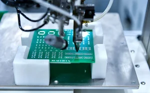
Laser drilling is widely used for small blind vias and microvias.
A controlled laser beam removes dielectric material and exposes the underlying copper pad. Compared with conventional mechanical drilling, laser drilling can produce much smaller holes and enables high-density interconnections.
Laser-drilled microvias are especially important for:
- Fine-pitch BGA packages
- Smartphones
- Wearable electronics
- High-density modules
- Miniaturized medical devices
3. Mechanical Drilling
Mechanical drilling can be used when the blind or buried via diameter is sufficiently large.
It provides good productivity for certain via structures but may have limitations when extremely small geometries or precise depth control are required.
4. Plasma Etching
Plasma etching can be used in specialized PCB manufacturing processes to selectively remove dielectric material and expose copper structures.
It can provide controlled dielectric removal for specific advanced interconnection technologies.
5. Via Plating
After drilling, the exposed hole walls must be metallized.
Copper plating creates a conductive connection between the intended PCB layers. Proper control of:
- Copper thickness
- Plating uniformity
- Hole-wall quality
- Surface preparation
- Current density
- Aspect ratio
is essential for reliable via performance.
Poor plating can result in increased resistance, voids, cracks, or intermittent electrical connections.
Important Design Considerations for Blind and Buried Vias
When designing a PCB with blind or buried vias, engineers must consider both electrical performance and manufacturing capability.
1. Via Diameter and Aspect Ratio
The relationship between via diameter and depth directly affects manufacturability.
A deeper and narrower via is generally more difficult to drill and plate reliably. Therefore, designers should work with the PCB manufacturer’s design rules before finalizing via dimensions.
2. Layer Stackup
The PCB stackup determines which layers can be connected using blind and buried vias.
A properly engineered stackup should consider:
- Signal layers
- Ground planes
- Power planes
- Dielectric thickness
- Copper thickness
- Controlled impedance
- Via transitions
A well-designed stackup can reduce unnecessary vias while improving signal integrity.
3. Signal Integrity
For high-speed PCB designs, unnecessary via transitions can introduce parasitic capacitance and inductance.
Blind and buried vias can reduce some unnecessary layer transitions and help maintain cleaner high-speed routing.
However, the via structure itself must still be modeled and controlled for high-speed interfaces.
4. Thermal Management
Copper-filled or copper-plated via structures can also contribute to thermal management when appropriately designed.
Thermal vias can transfer heat from hot components into internal or bottom copper structures.
5. Manufacturing Tolerances
Blind and buried via designs require tight registration between layers.
Manufacturers must control:
- Drilling accuracy
- Layer alignment
- Hole diameter
- Copper plating thickness
- Lamination registration
- Pad size
- Via-to-copper clearance
Poor registration can cause via breakout or unreliable electrical connections.
Applications of Blind and Buried Via PCBs
Consumer Electronics
Smartphones, tablets, laptops, smartwatches, and other compact electronic devices commonly require high-density interconnection technologies.
Blind and microvia structures allow engineers to route signals underneath fine-pitch components while maximizing available PCB space.
Telecommunications
High-speed networking equipment, wireless communication modules, routers, switches, and other telecommunications systems can use advanced via structures to support dense routing and high-speed signal transmission.
Automotive Electronics
Modern vehicles contain increasingly complex electronic systems, including:
- Electronic control units
- ADAS systems
- Infotainment systems
- Radar modules
- Sensor systems
- Vehicle networking modules
Blind and buried vias can help meet the space and routing requirements of these systems.
Aerospace and Defense
Aerospace and defense electronics require compact, reliable, and high-performance interconnections.
Blind and buried vias can support dense multilayer designs where PCB space is limited and electrical performance is critical.
Medical Electronics
Compact diagnostic and monitoring equipment can benefit from high-density PCB technologies.
Applications may include:
- Portable monitoring equipment
- Medical imaging electronics
- Diagnostic instruments
- Patient monitoring systems
- Wearable medical devices
Advantages of Blind and Buried Vias
The main advantages of blind and buried vias include:
Higher Routing Density
By connecting only selected PCB layers, blind and buried vias free up valuable routing space.
This is particularly beneficial for high-density PCB and HDI designs.
Smaller PCB Size
More efficient vertical interconnections allow engineers to reduce board dimensions without sacrificing functionality.
Improved Component Fan-Out
Blind microvias are particularly useful for routing signals from fine-pitch BGA packages.
Better Space Utilization
Because buried vias do not occupy the external PCB surfaces, designers have more freedom for component placement and surface routing.
Potential Signal Integrity Benefits
Reducing unnecessary via transitions can help minimize parasitic effects and improve high-speed signal routing when the stackup and via geometry are properly engineered.
Disadvantages of Blind and Buried Vias
Despite their advantages, these technologies also have several limitations.
Higher Manufacturing Cost
Blind and buried vias require more advanced fabrication processes than conventional through-hole vias.
More Complex Manufacturing
Sequential lamination, laser drilling, precision registration, and additional inspection steps can increase manufacturing complexity.
More Difficult Inspection
Buried vias cannot be visually inspected from the external PCB surface.
Advanced inspection and electrical testing may therefore be required.
Higher Design Requirements
Designers must work within the manufacturer’s capabilities, especially regarding:
- Minimum via diameter
- Aspect ratio
- Layer-to-layer registration
- Pad dimensions
- Copper thickness
- Sequential lamination capability
How to Choose a Blind and Buried Via PCB Manufacturer
Selecting the right blind and buried via PCB manufacturer is critical because these boards require tighter process control than standard PCBs.
A qualified manufacturer should have experience with:
- HDI PCB manufacturing
- Laser drilling
- Sequential lamination
- Microvia technology
- High-precision copper plating
- Advanced AOI inspection
- X-ray inspection
- Electrical testing
- Controlled impedance manufacturing
- High-density BGA routing requirements
At Kingda, advanced PCB manufacturing capabilities can help customers transform complex PCB designs into manufacturable products while maintaining strict process control and quality requirements.
A reliable manufacturing partner should also provide engineering support during the DFM stage. Early review of the stackup, via structure, drill dimensions, copper thickness, and layer registration can help prevent expensive redesigns later in the production process.
Blind and Buried Vias: Frequently Asked Questions
Are blind vias visible on a PCB?
Yes. A blind via begins on the top or bottom surface of the PCB, so its opening can generally be observed from the corresponding external layer.
Can buried vias be seen from the outside?
No. Buried vias are located entirely inside the PCB stackup and do not reach either external surface.
Are blind vias more expensive than through-hole vias?
Generally, yes. Blind vias require additional process control and may involve laser drilling or sequential lamination, increasing manufacturing costs.
Are buried vias more expensive than blind vias?
In many designs, yes. Buried vias commonly require additional internal fabrication and lamination processes, although the actual cost depends on the PCB stackup and manufacturing method.
Are blind and buried vias suitable for high-speed PCBs?
Yes. They can be useful in high-speed PCB designs because they enable more efficient routing and can reduce unnecessary layer transitions. However, via geometry, impedance, return paths, and stackup must be carefully designed.
Conclusion
Blind and buried vias are important technologies for modern high-density and multilayer PCB manufacturing. A blind via connects an external layer with one or more internal layers, while a buried via connects internal layers without reaching the PCB surface.
Compared with conventional through-hole vias, they provide better space utilization and greater routing flexibility, making them particularly valuable for HDI PCB, smartphones, telecommunications equipment, automotive electronics, medical devices, aerospace systems, and other compact electronic products.
However, these advanced via structures also require more sophisticated design and manufacturing processes. Laser drilling, sequential lamination, precision copper plating, accurate layer registration, and comprehensive electrical inspection all play important roles in ensuring reliable PCB performance.
For engineers developing high-density or miniaturized electronic products, selecting the right via structure at the design stage can significantly influence PCB size, routing density, signal integrity, manufacturing cost, and long-term reliability. Working with an experienced blind and buried via PCB manufacturer such as Kingda can help ensure that complex via structures are optimized for both performance and manufacturability.