Ceramic PCB Fabrication: Alumina, AlN and DBC Technology
There is a point in a design where the thermal path stops being a layout problem and becomes a material problem. A power module that has to move tens of watts through a surface the size of a postage stamp, a radio that must hold its impedance at ten gigahertz, or a circuit that must operate where the ambient temperature exceeds the rating of ordinary laminate, all lead to the same family of substrates. Ceramic PCB technology exists for those cases.
When FR4 Is Not Enough
Glass reinforced epoxy is a good insulator and a poor conductor of heat, with a thermal conductivity of a few tenths of a watt per metre kelvin. That is adequate for a processor dissipating a couple of watts, and inadequate for a device dissipating fifty. The dielectric strength is also finite, so high voltage insulation in a thin laminate requires tracking distance that costs area.
A ceramic substrate answers both limits. Its thermal conductivity is two orders of magnitude higher than FR4 in the better materials, its dielectric strength is high enough to allow compact high voltage layouts, and its expansion behaviour can be matched to silicon so that a large die does not tear its own solder joints apart during thermal cycling.
Substrate Materials and What They Offer
Alumina is the workhorse. It is mechanically strong, chemically stable, well understood and comparatively inexpensive, with a thermal conductivity in the range of twenty to thirty watts per metre kelvin. It suits industrial power supplies, high voltage circuits and applications where the thermal load is moderate.
Aluminium nitride is chosen when the thermal load is severe. Its thermal conductivity is roughly five times that of alumina, which makes it the natural substrate for insulated gate bipolar transistor modules, silicon carbide power devices and traction inverters. It costs more and is harder to process, and its mechanical strength is lower, so the design has to avoid the sharp corners and thin sections that alumina tolerates.
Beryllium oxide has the highest thermal conductivity of the common ceramics but is rarely used because of the health hazard associated with its dust. Low temperature co-fired ceramic occupies a different niche: it supports multiple layers with embedded passive components and is well suited to radio frequency modules, while high temperature co-fired ceramic is used where the environment demands the highest reliability.
<img src="https://www.gopcba.com/wp-content/uploads/2025/05/DIP拉线风彩.jpg" alt="Direct bonded copper substrate on a ceramic base” />
Direct Bonded Copper and Plated Copper
The earliest and still the most common way to put conductors on a ceramic is the direct bonded copper process. A copper sheet is placed on the ceramic and heated until a thin oxide layer forms at the interface and bonds the two together. The result is a thick copper layer, typically one hundred to four hundred micrometres, which is exactly what a power module needs because it carries large currents and spreads heat laterally.
The alternative is direct plated copper, in which a seed layer is deposited and copper is electroplated through a pattern. It produces much finer features, with line widths below seventy five micrometres, at the cost of a thinner conductor. The choice between them is therefore a choice between current and resolution, and a board that must do both may use one process for the power area and another for the control area.
Multilayer Ceramic and Buried Passives
Ceramic substrates can be built as multilayer structures, either by laminating green sheets and co-firing them or by building up layers on a fired substrate. Multilayer construction allows a ground plane beneath a radio frequency circuit, embedded capacitors and resistors, and the routing density that a dense module requires without the dielectric losses of a polymer laminate.
The design rules differ from those of an ordinary multilayer board. Via formation, shrinkage during firing, conductor shrinkage and the registration achieved between layers all constrain the geometry, and the design has to be adapted to the process rather than the other way round. The options for interconnecting layers are comparable in concept to those of a conventional board and are described in via in pad or plated through.
Design Rules for a Brittle Substrate
Ceramic does not yield. It fails suddenly, and a stress concentration that would be absorbed by a polymer laminate becomes a crack. Corners should be rounded, the copper distribution should be balanced across the panel so that the shrinkage during firing is uniform, and the substrate should be thick enough for the mechanical handling it will see and thin enough for the thermal path it must provide.
Copper thickness is chosen for the current and for the heat spreading rather than for impedance. A DBC substrate with a heavy copper layer can carry a large current with a modest temperature rise, and the relationship between thickness, width, current and temperature is the same one that applies to any board, as described in trace width and current calculation. The same reasoning applies to the pad geometry used under a power device, which is discussed in PCB pad design standards.
Assembly and Attach Processes
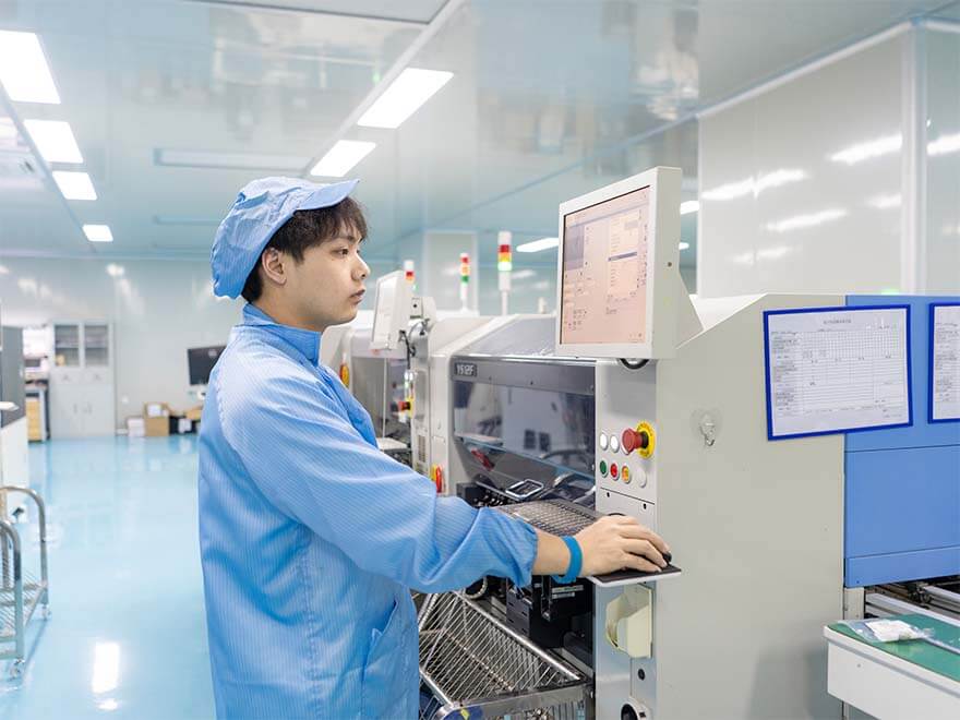
Assembly on ceramic is a high temperature process. A die is attached with a solder or a sintered silver layer, wires are bonded to the metallisation, and the whole assembly is often soldered to a heat sink or a baseplate. The metallisation therefore has to be compatible with the attach process: a thick copper surface suits soldering and sintering, while a gold finish is chosen where aluminium or gold wire bonding is used.
The thermal interface between the substrate and the heat sink is part of the same design. A thermal interface material, a soldered joint or a direct bond to a metal baseplate all determine how much of the heat generated at the junction actually leaves the module, and a substrate with excellent conductivity attached to a poor interface performs no better than an ordinary board.
Inspection and Qualification
Inspection of ceramic substrates looks for cracks, voids at the copper to ceramic interface and defects in the metallisation, and it uses optical inspection, X-ray and, where the requirement justifies it, thermal imaging to verify the temperature distribution under load. The bond quality at the DBC interface is confirmed by thermal cycling, which is also where a poor substrate reveals itself first.
Qualification for a power application is a combination of thermal cycling, power cycling, high temperature storage and dielectric withstand testing. Automotive projects add the requirement to work to the applicable quality management system and to demonstrate that the processes are under statistical control, which is a reasonable test of whether a supplier can produce the same substrate twice. A qualification that is only performed on the first article proves the design; a qualification that is repeated on production lots proves the process.
Where a ceramic substrate replaces a metal backed board, the comparison is worth making before the design is committed. A thin dielectric on an aluminium base gives a good thermal path at a lower cost, and it is adequate while the working voltage and the temperature remain within the limits of the polymer layer. The ceramic becomes the necessary answer when that layer is no longer good enough.
FAQ
Is a ceramic PCB always more expensive than FR4? Yes, and by a wide margin. It is chosen when the thermal or high frequency requirement cannot be met otherwise, or when the reliability of the module justifies the cost.
Which ceramic should be used for a power module? Alumina for moderate power and high voltage, aluminium nitride where the thermal load is high and the substrate is the limiting path.
Can a ceramic board carry fine geometry? Yes, with the plated copper process. Direct bonded copper gives a thick conductor with coarser features, so the two processes are often combined on one substrate.