Ceramic Substrates for Automotive Thermoelectric Coolers
A thermoelectric cooler is a solid state heat pump. Current through a junction of p type and n type semiconductor pellets moves heat from one face of the module to the other, so the same device can cool a component or stabilise its temperature depending on the direction of the current. Automotive applications use both modes, from seat and cabin comfort systems to the thermal control of laser radar transmitters, camera housings and battery conditioning plates.
Mechanically the module is simple: a row of pellets sandwiched between two ceramic plates. Electrically and thermally it is demanding. The ceramic substrate must pass a large current with minimal voltage drop, remove or deliver heat across its thickness, isolate the electrical circuit from the metal housing, and survive the thermal cycling that follows every change of set point. Choosing that substrate is the decision that sets the life of the module.
What a Thermoelectric Cooler Asks of Its Substrate
The first requirement is electrical isolation with low thermal resistance. The pellets are connected in series by copper pads on the inner face of each plate, and the outer face is often bonded to a heat sink or a housing that is electrically grounded. The ceramic has to hold off the full module voltage while conducting heat efficiently, and those two requirements pull in opposite directions in most materials.
The second requirement is dimensional stability. The pellets are rigid and the soldered joints are thin, so any differential expansion between the ceramic, the copper pads and the solder is concentrated in a joint a few tens of micrometres thick. A substrate with a thermal expansion coefficient that is far from that of the copper and the solder accelerates fatigue at that joint, which is the most common failure mode in the field.

Alumina and Aluminium Nitride Compared
Alumina remains the default choice. It is inexpensive, mechanically strong, chemically stable and available in large panels with consistent thickness. Its limitation is thermal conductivity of roughly 24 to 30 watts per metre kelvin, which is adequate for low power modules but becomes the dominant thermal resistance as the pumping capacity of the module increases.
Aluminium nitride conducts heat at 170 to 230 watts per metre kelvin, several times better than alumina, and its expansion coefficient of about 4.5 parts per million per degree is closer to silicon and to the copper used for metallisation. The penalty is cost and process difficulty: the powder is sensitive to oxygen contamination, which lowers conductivity, and the material is harder to machine. In modules where the ceramic is the limiting thermal resistance the substitution usually pays for itself, and the same trade off appears in general thermal management design for power electronics.
Metallisation Options
Direct bonded copper is the most common metallisation. A copper foil is bonded to the ceramic at high temperature, producing a strong interface with excellent current capacity and good thermal spreading. The bond strength is high, but the process needs a copper thickness that can be patterned to suit the circuit, and thick copper on a thin ceramic introduces residual stress that must be managed in the layout of the pads.
Active metal brazing uses a brazing alloy to join copper or another metal to the ceramic, giving a thinner joint and better performance on nitride ceramics that are difficult to bond directly. Thick film metallisation, printed and fired onto the surface, is cheaper and suits lower current circuits and sensor connections, though the adhesion and current capacity are below those of the bonded alternatives.
Thermal Cycling and Solder Fatigue
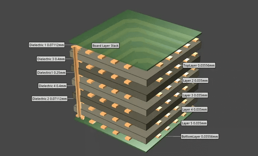
The pellets are usually attached with a bismuth tin or a lead free solder, and the pads on which they sit are copper bonded to ceramic. When the set point changes, the copper and the ceramic expand by different amounts and the solder joint absorbs the difference. Cracks start at the corner of the joint and propagate across it, raising the junction resistance and eventually opening the circuit. The number of cycles the joint survives depends on the joint thickness, the pad geometry and the expansion mismatch.
Design measures that help include keeping pads rounded rather than square, providing a defined stand off thickness for the solder, and avoiding any discontinuity in the copper pattern that would concentrate strain. Where the module will see thousands of cycles, an aluminium nitride substrate with a matched expansion coefficient reduces the strain at source rather than compensating for it, and this is often the deciding argument in favour of the more expensive material.
Assembly, Isolation and Clearance
Because the substrate carries the working voltage of the module across a thin plate, creepage and clearance requirements apply to the edges of the metallisation and to the mounting hardware. Conductive paste or a thermal interface material is normally used between the outer face and the heat sink, and that material must also be electrically insulating if the heat sink is grounded. Fasteners that pass through the ceramic need a compliant washer, and the tightening torque must be specified, since ceramic cracks rather than yields when it is overloaded.
Automotive modules are usually sealed and often coated. A protective coating over the metallisation protects against condensation and salt spray, and it must be selected so that it does not interfere with the thermal path or with the soldering of the pellets. Where the module is expected to operate at high humidity, the coating also reduces the risk of electrochemical migration between adjacent pads. The same logic that governs conformal coating on a conventional board applies here, with a harsher environment to withstand.
Reliability Testing
Qualification for an automotive thermoelectric module typically combines thermal cycling between fixed extremes, high temperature storage, humidity and bias, and mechanical shock and vibration. Power cycling is run in addition to temperature cycling because the current pulse imposes a thermal gradient across the pellets that a temperature chamber alone does not reproduce. Measuring the alternating current resistance of the module during the test tracks the growth of joint damage and gives an early indication of degradation.
For the substrate itself, the useful checks are the initial thermal resistance, the dielectric strength after cycling, the adhesion of the metallisation and a cross section of the joints after the test is complete. Any change in the ceramic supplier, the copper thickness or the brazing alloy should trigger a repeat of the thermal cycling test, because the failure mechanism depends on all three and a small process change can move the cycle life substantially. A design validated with these measurements is far more likely to meet the durability targets of the vehicle programme it serves.
Related reading: our fabrication notes, board quality and design release notes cover the same ground.
FAQ
Should the ceramic substrate in a thermoelectric cooler be alumina or aluminium nitride? Use alumina where the module power is low and cost dominates. Move to aluminium nitride when the ceramic is the main thermal resistance or when a long thermal cycling life is required.
Why does the solder joint fail before the ceramic? Because the joint is the thinnest and most compliant element, so it absorbs the whole expansion mismatch between the pellets, the copper and the ceramic. It is designed to be the weakest link, and the design task is to slow its fatigue.
Can a thermoelectric module heat as well as cool? Yes. Reversing the current reverses the direction of heat transport, which is why the same assembly is used for temperature stabilisation, where the controller moves the set point in both directions.