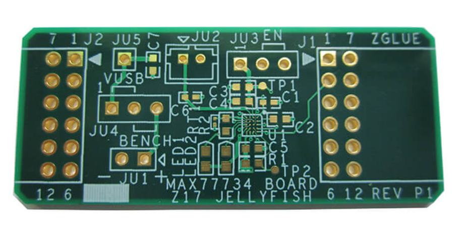
Circuit Board Components: From Resistors to Integrated Circuits
Every circuit board is a network of a handful of component families, connected by copper. Knowing what each family does, how it fails and how it is placed is the difference between a layout that works and one that works once.
Resistors: The Most Common Component
Resistors set current, divide voltage and terminate signals. In surface mount form they are among the easiest parts to place and the most frequently mis-valued, which is why a design review should verify every value against the schematic rather than trusting the bill of materials.
Technology matters at the extremes. A thin film resistor holds tolerance and temperature coefficient better than a thick film part, and a current sense resistor is chosen for its low temperature coefficient and its power rating rather than for its tolerance alone.
Capacitors and Their Real Behaviour
Capacitors store energy, decouple supplies and set time constants, but their behaviour depends strongly on the dielectric. A ceramic capacitor is small and inexpensive, and the high-capacitance variants lose a large fraction of their nominal value under DC bias, which is why a 10 µF part may behave as 3 µF at the applied voltage.
Electrolytic capacitors provide large capacitance in a small volume but have a limited life that depends on temperature, and their equivalent series resistance rises as they age. In power circuits that resistance decides the ripple, so the capacitor life is a design parameter rather than a purchasing detail.

Inductors and Magnetic Behaviour
Inductors store energy in a magnetic field and are central to switching regulators and filters. Their key parameters are inductance, inductor saturation current and DC resistance, and a design that satisfies the first while exceeding the second will produce a supply that fails under load.
Magnetically, an inductor is the component most likely to disturb its neighbours. Placing one near a sensor, a high-impedance node or a low-level audio path couples switching noise directly into the signal, and the coupling is not removed by filtering the power rail.
Diodes, Transistors and Switches
Diodes steer current and protect circuits from reverse polarity and inductive kickback. Transistors amplify or switch, and the choice between a bipolar device and a field effect device follows the drive conditions: a MOSFET needs a voltage on its gate, while a bipolar transistor needs base current.
Package selection is part of the decision. A small package has higher thermal resistance, so the same die in a smaller outline runs hotter, and a design that ignores that relationship will find its switching device cycling into thermal shutdown.
<img src="https://www.gopcba.com/wp-content/uploads/2026/09/266-3-scaled.jpg" alt="Fine pitch integrated circuit package with escape routing on a PCB” />
Integrated Circuits and Package Types
Integrated circuits are grouped by function rather than by technology. Analog devices such as operational amplifiers and regulators, digital logic, memory, microcontrollers and specialized interface chips each carry their own layout expectations.
The package determines much of the layout work. A small outline package needs a modest courtyard, a quad flat pack needs careful pad geometry and a ball grid array needs fanout and via planning, because the connections are underneath the device where they cannot be probed. Escape routing for a fine-pitch package is usually the constraint that decides the layer count.
Crystals, Oscillators and Timing
Timing devices set the pace of the system, and they are sensitive to layout in ways that are easy to underestimate. A crystal must be placed close to its driver, with short traces, a local ground reference and a guard ring where the design permits.
Load capacitance must match the crystal specification, and it must include the parasitic capacitance of the traces. A mismatch produces a frequency error that is small enough to pass a functional test and large enough to break a communication protocol at the edge of its tolerance.
Connectors, Switches and Mechanical Parts
Connectors carry the electrical interface and a substantial share of the mechanical load. Their pad geometry, retention features and keep-outs belong on the layout from the beginning, because moving a connector later changes the enclosure.
Switches, jumpers, test points and mounting hardware are easy to treat as afterthoughts, and they are the parts most often found to be inaccessible after assembly. Placing them so that a probe or a finger can reach them is a design decision, not a manufacturing detail.
Selecting Components for Manufacturability
Availability and packaging decide whether a design can be built as intended. A part that is only available in a large minimum order, or only in a package the placement machine cannot feed reliably, adds cost that never appears in the schematic.
The practical approach is to standardise on a small set of packages and values, prefer parts with multiple sources and check lifecycle status before the design is released. Many of these issues surface during the review of PCBA development, and reading the component list alongside SMT placement practice reveals the packages that will be difficult to assemble.
Component Placement Priorities
Placement is where component knowledge turns into a working board. Decoupling capacitors go beside the pin they serve, not in a tidy row at the edge of the device. Crystals go next to their driver with the shortest possible traces. Series termination resistors go near the source, and bulk capacitors go near the load that draws the current.
Then the noisy parts move away from the sensitive ones. Switching regulators, inductors and clock generators belong in one region, while analog front ends, sensors and reference circuits belong in another, separated by distance and by their return paths rather than only by a line on the drawing.
Mechanical components override electrical preferences. A connector at the board edge, a mounting hole or a keep-out for the enclosure fixes the position of everything near it, so those parts should be placed first and the electrical optimisation performed around them.
Reading a Datasheet for Layout Clues
Most datasheets contain a recommended layout section, and it is there for a reason. The land pattern, the thermal pad geometry, the suggested decoupling arrangement and the keep-out around an antenna or a crystal are the manufacturer telling you which layout practices have caused failures.
Two details are worth checking consistently. The first is whether the recommended land pattern includes a solder mask expansion, because some vendors specify the copper and leave the mask to the designer. The second is the thermal pad, which needs an array of vias and a paste pattern that avoids voids, not simply a solid copper area.
Component selection and layout are the same activity viewed at different times. Choosing a part without reading how it must be placed usually means discovering afterwards that the package cannot be routed, and the conventions in pad design standards are a useful cross-check before the design is released.
FAQ
How do I choose between ceramic and electrolytic capacitors? Use ceramic for decoupling and for small values, and electrolytic where large capacitance is needed at moderate frequencies. In most power supplies the two work together, with the electrolytic providing bulk storage and the ceramic handling the high-frequency current.
Why does my regulator fail under load? The most common causes are an inductor that saturates above the operating current and a capacitor whose effective capacitance is much lower than its nominal value. Both are specification errors rather than layout errors.
What component causes the most layout problems? Fine-pitch integrated circuits, because their fanout determines the layer count and the via structure. Deciding the escape strategy early is the single most useful thing a designer can do, as described in escape routing and fanout.