Design For SMT Assembly: What The Line Needs
A board is assembled by machines that have requirements of their own, and those requirements are cheaper to satisfy during layout than to work around during production. Design for assembly is not a set of arbitrary rules; each one comes from a physical constraint of the printer, the placement machine or the reflow oven.
This article describes those constraints, the layout features that accommodate them, and the checks that catch a board that would be difficult to build.
Most of the requirements are known at the start of a design and cost nothing to meet. The ones that are discovered after the artwork is released usually cost a revision.
Panelisation And Handling
The assembly line handles panels rather than single boards, and a panel needs rails for the conveyor, fiducials for the machines to locate, and a separation method that leaves the finished board intact. The rail width and the panel dimensions are set by the equipment, and the number of boards on a panel determines the efficiency of the whole process.
Panelisation also has to respect the assembly process. A panel that is too large will sag in the oven; one that is too small wastes machine time. Where the board is small, multiple copies are placed on a panel and separated afterwards, and the placement order and pad positioning requirements then apply to each copy.
Fiducials And Machine Vision
Every machine that places or inspects something needs to know where the board is. Fiducials are the marks it uses, and they must be placed where the machine can see them: globally on the panel for coarse alignment, and locally near fine pitch devices for the accuracy those devices need.
A fiducial is a copper dot with a clearance around it and no solder mask over it, sized and shaped to the machine’s preference. Two or more global fiducials, ideally asymmetric so that rotation is unambiguous, and a pair near each fine pitch array are the usual arrangement. A board without fiducials relies on the panel edges, which is not accurate enough for modern components.
Stencil And Paste Printing
The stencil is a thin sheet of metal with apertures that deposit paste onto the pads, and its design is derived from the pad geometry. The aperture area relative to the pad area controls the volume of paste, and the volume controls the joint. Apertures that are too small release paste poorly; those too large deposit too much and cause bridging.
Several layout features affect the printing step. The pad area relative to the aperture must be within the process window, which is why very small pads need a thinner stencil rather than a smaller aperture. The pad finish affects how the paste wets and how the stencil releases. And the area around the pads should be free of features that the squeegee might catch on.

Placement And Component Spacing
The placement machine approaches a component from above with a nozzle, and it needs clear space around the position. Components placed too close together can be disturbed by the nozzle of a neighbouring placement, and tall components can block the head’s path to a lower one. The machine’s approach direction should be considered when similar parts are grouped.
Component orientation also matters. Parts that must be placed in a particular rotation should be arranged so that the rotation is consistent, which reduces the number of nozzle changes and the risk of a programming error. Where a part can be placed in only one orientation because of an asymmetric pad pattern, that should be visible on the footprint rather than relying on the machine vision.
Reflow And Thermal Considerations
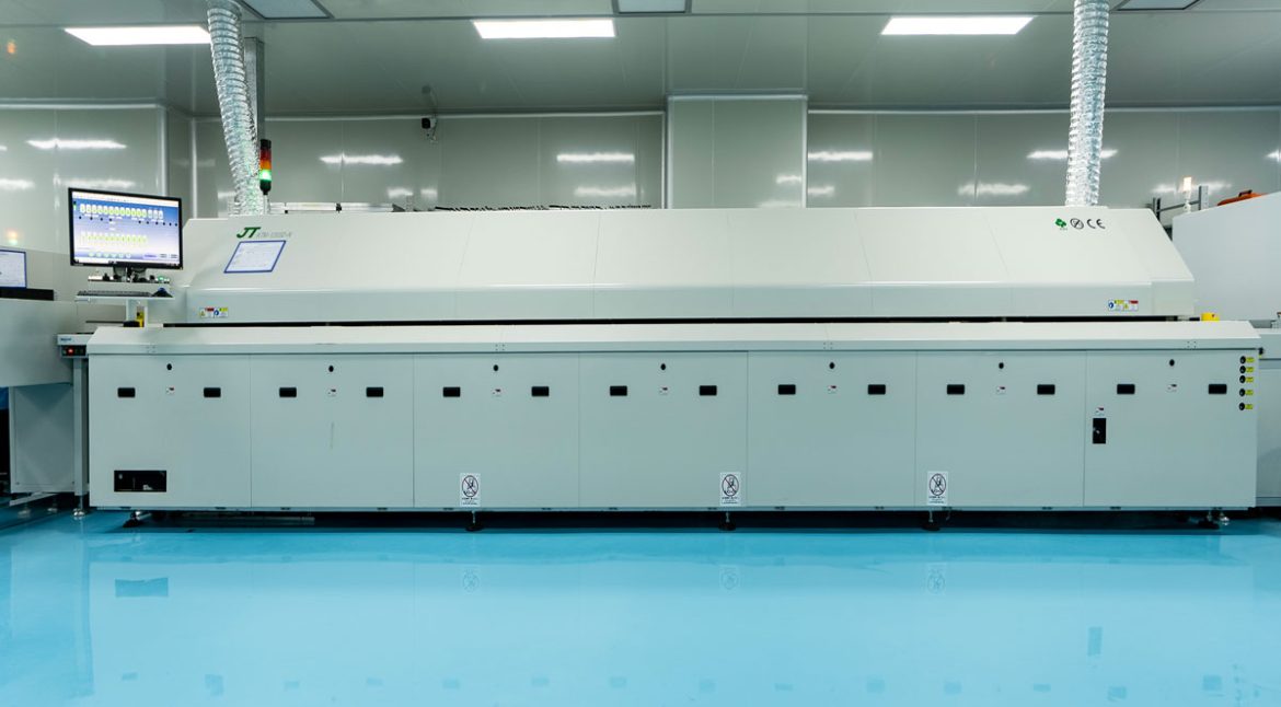
The reflow profile is set by the largest thermal mass on the board, and a board with a very large component beside a very small one is difficult to profile. The large component needs enough heat to wet its joints while the small one and its neighbours must not be overheated.
The layout response is to group components of similar thermal mass where possible, and to avoid placing a small package in the shadow of a large one where the airflow will be restricted. Where a large thermal mass cannot be avoided, the profile should be developed with that board rather than transferred from a previous product. The mechanisms behind component movement during reflow are worth understanding when a design has an unusual mass distribution.
Inspection And Rework Access
After reflow, the board is inspected optically, and the camera needs a line of sight. Components placed in the shadow of a tall neighbour cannot be inspected, which means a defect there will be found later or not at all. Leaving a little space around fine pitch devices costs board area and buys inspectability.
Rework access is the related requirement. A component that can be reached with a hot air nozzle and a soldering iron can be replaced; one surrounded by tall parts cannot. Where a device has a low yield or is likely to be updated, the space around it is a deliberate investment.
Checks Before Release
The checks that catch most assembly problems are straightforward. Confirm the panel drawing, the fiducials and the tooling holes. Confirm the stencil apertures against the pad area ratio and the stencil thickness. Look for components that are too close to a neighbouring position or that block the line of sight for inspection. And confirm the space around any device that may need rework.
Most of these are covered by a manufacturability review, and the design guidelines for manufacture are the reference for the rest. The review is worth performing with the assembly house rather than alone, because the equipment and the process window are specific to the line that will build the product.
Additional Considerations for This Build
Practical attention to SMT assembly pays for itself here, because it decides whether the finished board behaves as the drawing intended. Where the requirement is not stated on the fabrication drawing or in the assembly notes, the shop has to assume a default, and that default is rarely the value the design was simulated with. Stating SMT assembly explicitly, together with the tolerance that applies, removes the assumption and keeps the result predictable from batch to batch.
Process Control and Verification
On a design of this kind, stencil is the item that decides how the rest of the board is arranged. Where a value sits close to a process limit, the drawing should say so, since the shop can then open the process window rather than working to a nominal figure that carries no tolerance. A stack-up that is drawn rather than described removes most of the ambiguity from a quotation, and it lets the fabricator price the board against the dielectric and copper weights that will actually be used.
Where the requirement is not written down, the shop supplies its own default, and the default is chosen for the process rather than for the design.
FAQ
How many fiducials does a panel need? At least three unconnected global fiducials for unambiguous alignment, plus local fiducials beside fine pitch devices where the placement accuracy requires them.
Can fiducials be placed under a component? No, they must be visible to the camera. They also must not be covered by solder mask, which is why a fiducial is defined as a mask opening rather than as a printed mark.
Does panelisation affect cost? It affects it substantially, because it determines how many boards fit on a panel and how much machine time each board consumes. A panel layout that fits more boards may be worth a small compromise in the board outline.