Dynamic Flex Design: Bend Radius, Grain and Copper
A flexible circuit that bends once during assembly and a flexible circuit that bends a million times in service are different designs. The difference is not the material alone but the geometry of the copper and the direction in which it is stressed.
Static and Dynamic Flex
A static flex is formed once and remains in that position. The bend is a manufacturing operation, and the circuit must survive the forming without cracking.
A dynamic flex moves repeatedly during the life of the product. The copper must withstand the accumulated strain of every cycle, and the design rules are far more restrictive.
The distinction determines the copper type, the bend radius and the layer count. A design that treats a dynamic flex as a static one will fail after a few thousand cycles. Our bendable materials notes describe the options.
Copper Type and Grain Direction
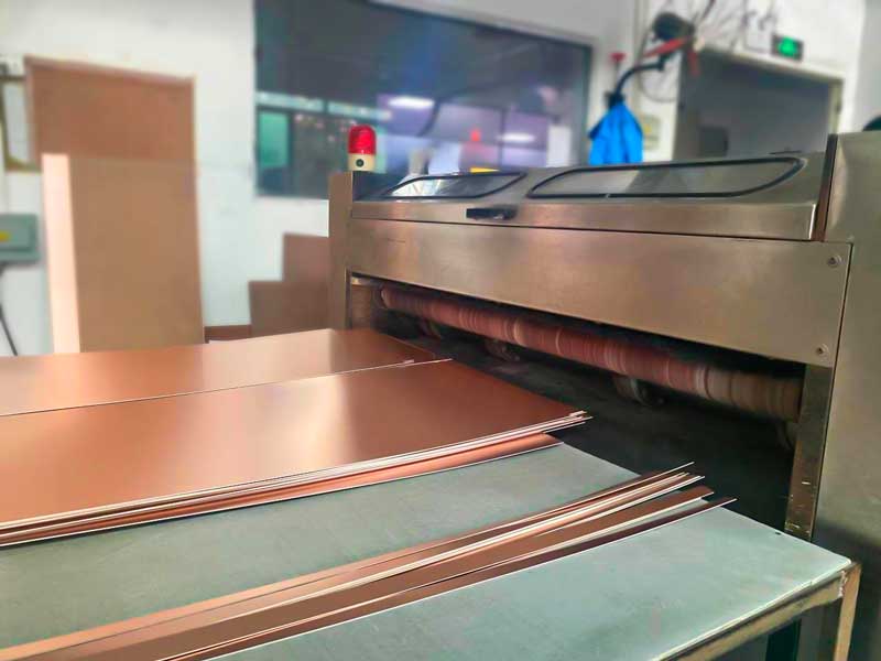
Rolled and annealed copper has a grain structure that is elongated in the rolling direction and it withstands bending far better than electrodeposited copper, whose grain is columnar and which cracks at the grain boundaries.
The grain direction matters because the copper is more ductile along the roll direction than across it. The bend line should therefore run across the roll direction, so that the copper is bent in its most ductile orientation.
On a flexible circuit, the roll direction is specified on the drawing and it is one of the few fabrication details that directly determines whether the part survives.
Bend Radius and Strain
The strain in the copper during a bend depends on the copper thickness and on the bend radius. A thinner copper and a larger radius both reduce the strain.
The usual design rule expresses the minimum bend radius as a multiple of the total thickness of the flexible stack, with a larger multiple required for a dynamic application than for a static one.
The copper should be placed in the neutral axis of the bend, which means using a coverlay on both sides and keeping the copper at the centre of the stack. A single sided flex has the copper at the surface, which is the worst case for strain. Our multilayer flexible notes describe how a symmetric construction is built.
The Bend Region
The bend region should contain no vias, no plated holes and no pads. A via is a hole through the copper with plating in it, and the plating cracks under repeated bending.
The copper in the bend region should be a solid plane or a set of wide traces rather than a fine pattern, because a narrow trace concentrates the strain and cracks first. Where a fine pattern is unavoidable, the bend radius must increase.
The coverlay should extend across the bend region and should be bonded over the full area, because a coverlay that has lifted provides no support. Where the bend is tight, a thinner coverlay adhesive helps.
Test Coupons and Verification
The verification is a bending test, either a static bend at the specified radius or a cyclic test at the specified radius and cycle count, with the resistance of the traces monitored.
The coupon should be built with the same construction as the product, since the copper type, the adhesive thickness and the coverlay all affect the result.
The test result is a cycle count to failure, and it should be compared against the requirement with margin. The margin accounts for the difference between a laboratory bend and the bends a user produces. Our quality notes describe how the result is recorded.
Handling After Fabrication
A flexible circuit can be damaged by bending at a radius smaller than its design minimum during handling, testing and assembly. The handling instructions should state the minimum radius and should be visible at the workstation.
A flex that must be held during assembly needs a support, either a stiffener or a fixture, so that the operator does not bend it. A stiffener bonded to the flex in the connector region is the standard solution.
Where the flex is folded into an enclosure, the fold should be formed with a tool at the specified radius rather than by hand. A hand formed fold is unpredictable and is a common cause of early failure. Our material properties notes describe the adhesive behaviour that affects the fold.
Assembly Considerations
Flexible circuits are usually assembled on a rigid carrier or in a panel and separated afterwards, because the material cannot be handled by standard equipment on its own.
The carrier constrains the flex during reflow, which prevents the dimensional change that would otherwise affect placement. Our design release checklist notes where the carrier requirement is recorded.
The flex must also be baked before assembly if it has absorbed moisture, and the bake must respect the adhesive’s temperature limit, which is lower than that of a rigid laminate.
Process Control and Verification
On a design of this kind, rolled copper is the item that decides how the rest of the board is arranged. Documenting the assumption is part of the design work, and a short note on the drawing prevents a question that would otherwise arrive a day later and cost a day of schedule. The process window is set by the narrowest step in the flow, so an improvement anywhere else shows up as margin rather than as yield until that step is addressed.
A short note on the drawing about handling, storage or packaging is often worth more than an extra decimal place on a tolerance. Where a value sits close to a process limit, the drawing should say so, since the shop can then open the process window rather than working to a nominal figure that carries no tolerance.
Process Control and Verification
On a design of this kind, rolled copper is the item that decides how the rest of the board is arranged. Documenting the assumption is part of the design work, and a short note on the drawing prevents a question that would otherwise arrive a day later and cost a day of schedule. The process window is set by the narrowest step in the flow, so an improvement anywhere else shows up as margin rather than as yield until that step is addressed.
A short note on the drawing about handling, storage or packaging is often worth more than an extra decimal place on a tolerance.
Process Control and Verification
On a design of this kind, rolled copper is the item that decides how the rest of the board is arranged. Documenting the assumption is part of the design work, and a short note on the drawing prevents a question that would otherwise arrive a day later and cost a day of schedule. The process window is set by the narrowest step in the flow, so an improvement anywhere else shows up as margin rather than as yield until that step is addressed.
FAQ
Can a rigid flex use electrodeposited copper? It can where the bend is static and the radius is generous. For a dynamic bend, rolled copper is required.
How many layers can a dynamic flex have? Fewer is better. Each additional layer increases the thickness and therefore the strain, and a single copper layer at the neutral axis is the most durable arrangement.
What does gopcb provide for flexible circuits? We provide copper type and grain direction specification, bend radius and construction recommendations for static and dynamic cases, bending test coupons with resistance monitoring, and handling instructions for assembly. Where a design asks a flex to do more than the construction supports, we say so before the panel is built.