Edge Plating and Castellations: Design and Process Limits
Edge plating turns the side wall of a board into a conductor, and castellations turn a row of plated barrels into a soldering interface for a module. Both are mechanical features that behave like electrical ones, which is why they have to be defined on the drawing rather than requested in a note. This article covers the sequence, the geometry and the inspection that keeps the plating continuous.
What Edge Plating Is
Edge plating is copper deposited on the side wall of a board, connecting features on the top and bottom surfaces around the perimeter. It is used for shielding, for grounding a module to a chassis, and for the castellations that let a small module be soldered onto a larger host board.
The plating is a continuous wrap rather than three separate features: copper has to be present on both surfaces and joined by a side wall that is conductive during plating. That requirement changes the panel layout, because the edge has to be exposed before the plating step rather than routed afterwards.
Castellations and Module Assembly
A castellated edge is a row of half holes, each one a plated barrel cut through the middle when the module was routed from the parent panel. The module then solders onto a host board the way a component does, with the half barrel providing the joint.
The critical dimensions are the finished half hole diameter and the remaining wall. A 0.9 mm finished hole leaves about 0.45 mm of half barrel, and the host pad has to be at least that wide with clearance for the fillet.
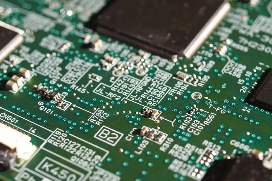
The half barrel is visible from the side after assembly, which makes castellation joints easier to inspect than a normal through hole hidden under a module.
Panel Layout for an Exposed Edge
For plating to reach the side wall, the panel needs a copper strip that will become the board edge, and the routing to final outline has to happen after plating. The edge is therefore not finished in the first operation, which changes the panel drawing and the coupon set.
The strip is typically 0.2 to 0.5 mm wide and is removed in a secondary routing pass. Because the edge is defined by plating, the mechanical tolerance of that final route becomes a plating tolerance and should be stated as one. The sequence is one of the points listed in our fabrication notes.
Plating Thickness on a Vertical Wall
Copper on a vertical wall is harder to control than on a flat surface, because current density at the panel edge is higher than in the centre. Typical requirements are 25 to 35 micrometres, measured on a microsection of a coupon that includes an edge sample. The measurement methods are described in our plating thickness guide.
Nickel and gold are added over the copper where a wear or contact surface is needed, and both follow the same edge effect. The measurement is taken on the section rather than with a surface gauge, because a gauge cannot see the wall.
Routing Sequence and the Finished Edge
Routing a plated edge removes plating from the cut surface unless the route is offset, so the sequence matters: route oversize, plate, then finish to the final outline. A second route that cuts into the plating leaves a burr and a discontinuity in the ground path.
Bit choice and feed rate matter more here than on an unplated edge, because the cut runs along a metal film that can smear over the laminate. Two shallow passes at a moderate feed leave a cleaner edge than one deep pass.
Solder Mask and Exposed Metal
Where the edge plating is itself the contact surface, mask has to be kept away from it, and the mask dam along the edge has to be wide enough that it does not bleed onto the metal. A bleed line across an edge contact is a short circuit risk rather than a cosmetic defect.
Where the plating is only a ground wrap, a mask window is normally left open at intervals so the chassis contact is defined. Those windows should be dimensioned, because an undefined window is decided by whoever prepares the artwork.
Mask bleed along a plated edge is easy to see on a section and almost impossible to judge from a photograph, which is why the edge appears in the coupon.
Assembly of Castellated Modules
A castellated module is placed like a fine pitch component and reflowed, and the paste volume for a half barrel is larger than for a flat pad of the same width. The stencil aperture is often a slot rather than a circle, and the joint forms around the outside of the barrel.
Cleanliness matters as well, because flux can be trapped in the gap between the module and the host board. The gap and the cleaning route should be considered together when the footprint is defined, using the requirements in our cleanliness guide.
Inspection and Verification
Edge plating is inspected visually for continuity around the perimeter and by a section on a coupon for thickness and wrap. Continuity is also confirmed electrically where the plating is a ground path, because a section shows thickness but not whether the plating reaches both surfaces.
Castellation joints are checked by X-ray or section, with the same criteria applied as to any through hole: fill, wetting and the absence of voids. The half barrel makes the joint visible from the side, which helps the inspection even when the joint is small.
Documentation
The drawing should state the plating thickness, the metals and their sequence, the width of the exposed edge, the tolerance on the final outline, and the finish applied to the castellations. A note asking for edge plating without those numbers leaves the process to be invented at the shop.
The panel drawing should show the oversize route and the final route and identify which coupon is used for the edge section. Where a module is cut from the panel, it should also show the order in which the two routes are performed.
Continuity is confirmed by measuring resistance from a test pad on the top surface to the plated edge and back to the bottom surface, on two opposite sides of the panel.
The exposed edge width is measured on the finished board rather than on the artwork, because etch and plating both move the boundary that the mask was drawn against.
Where the edge plating carries radio frequency current, the transition from the surface trace to the wall is kept short, because the corner adds inductance that the ground wrap exists to avoid.
FAQ
Can edge plating be added to an existing design? Only if the panel layout is changed to expose the edge before plating, because the plating cannot be applied after the outline has been routed.
How wide should a castellation be? The half barrel is set by the drill, so a 0.9 mm finished hole gives about 0.45 mm of contact, and the host pad should be at least that wide.
Does edge plating change the board outline tolerance? Yes, the final route defines the plated edge, so the outline tolerance becomes the tolerance of the electrical feature as well as of the mechanical one.