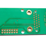
Solder Paste Printing on Flexible Substrates
Printing paste onto a flexible substrate is the same process as printing onto a rigid board and it behaves differently in every detail. The material moves, the carrier decides the flatness and the stencil release depends on the support underneath.
Why the Substrate Matters
The flexible material is thin and compliant. It will conform to whatever is beneath it, which is an advantage for support and a disadvantage for consistency, because a variation in the support becomes a variation in the board.
The material also moves with temperature and with humidity more than a rigid laminate, so the artwork and the stencil must both account for the same scale factor. Where the stencil was made for the rigid version of the artwork, the apertures will be offset.
The surface is often covered with a coverlay rather than a soldermask, and the coverlay’s thickness and its adhesive behave differently during printing. Our bendable materials notes describe the construction.
Carriers and Support
A flexible circuit is almost always printed while attached to a rigid carrier or held in a fixture that gives it the flatness of a rigid board.
The carrier must locate the flex by its tooling holes and hold it flat without stretching it. A carrier that stretches the material shifts every aperture relative to its pad.
The flex is often supplied attached to a rigid carrier by the fabricator, in a panel format that the assembly line can handle with standard equipment. Our multilayer flexible notes describe how the panel is arranged.

Stencil and Aperture Considerations
The stencil release depends on the area ratio as for any board, and the flex’s flatness affects the gasket between the stencil and the surface.
Where the coverlay creates a step, the stencil cannot sit flat and paste is pushed under it. The step must be accommodated by a relief in the stencil, a local reduction in thickness or a change to the coverlay layout.
The aperture pattern may need to differ from the rigid version of the same design, because the pad sizes and the coverlay openings are not identical. Our paste volume notes describe the aperture design.

Placement and Reflow
Placement on a flex uses the same machine and the same vision system, and the fiducials must be visible through the coverlay or provided on the copper.
The reflow profile must respect the flex’s adhesive limits, which are lower than a rigid laminate’s. The material must be baked before assembly at a temperature the adhesive tolerates.
The coefficient of expansion of the flex is different from the component’s, which affects the joint stress after reflow. Where the flex is thin, the assembly tends to warp and the support during reflow matters. Our quality notes describe the inspection of the finished joints.
Handling After Printing
The printed flex must be handled without flexing, because flexing the paste deposits disturbs them and produces bridging or missing paste.
Where the panel must be moved to the placement machine, the carrier should remain attached until the reflow is complete. Separating the flex from the carrier before assembly is a common cause of defects.
The handling instructions should be part of the assembly documentation rather than a verbal caution, because the people who handle the panels change.
Defects Specific to Flex Printing
Paste smearing appears where the flex has lifted from the carrier or where the coverlay step has forced the stencil up.
Missing deposits appear where the stencil did not seal against the surface, which is usually a support or flatness problem rather than an aperture problem.
A shift of the whole print relative to the pads indicates a scale difference between the stencil and the material, which points at the artwork compensation rather than the printer.
Verification
The verification is a paste inspection of the printed deposits on the first article and on a sample during production, using the same measurement as for a rigid board.
The deposit volume and the position should both be measured, since flex printing is prone to shifts rather than to volume errors.
The final verification is the joint inspection after reflow, where a support problem usually shows as a pattern of defects across a region rather than at individual pads.
Process Control and Verification
On a design of this kind, flexible substrate is the item that decides how the rest of the board is arranged. A stack-up that is drawn rather than described removes most of the ambiguity from a quotation, and it lets the fabricator price the board against the dielectric and copper weights that will actually be used. Where the requirement is not written down, the shop supplies its own default, and the default is chosen for the process rather than for the design.
The measurements that matter are the repeatable ones: conductor width and spacing, annular ring, finished hole size, plating thickness and surface finish are all verifiable on a coupon that travels with the panel. Running a first article through the same checks as the production panel confirms that the two agree, and that comparison is the cheapest form of process control available at prototype stage.
Keeping a sample from the panel turns a dispute into a measurement, because the same coupon can be re-examined by both parties without rebuilding the batch. Reviewing the design before the data is released is cheaper than correcting it after the panel is in the tank, because every step downstream inherits the decision made at the front end.
Process Control and Verification
On a design of this kind, flexible substrate is the item that decides how the rest of the board is arranged. A stack-up that is drawn rather than described removes most of the ambiguity from a quotation, and it lets the fabricator price the board against the dielectric and copper weights that will actually be used. Where the requirement is not written down, the shop supplies its own default, and the default is chosen for the process rather than for the design.
The measurements that matter are the repeatable ones: conductor width and spacing, annular ring, finished hole size, plating thickness and surface finish are all verifiable on a coupon that travels with the panel.
Process Control and Verification
On a design of this kind, flexible substrate is the item that decides how the rest of the board is arranged. A stack-up that is drawn rather than described removes most of the ambiguity from a quotation, and it lets the fabricator price the board against the dielectric and copper weights that will actually be used. Where the requirement is not written down, the shop supplies its own default, and the default is chosen for the process rather than for the design.
FAQ
Can a flexible circuit be printed without a carrier? Only where it is held flat by a vacuum table or a fixture that performs the same function. Without support the print is inconsistent.
Does the stencil for a rigid board work for the flex version? Only if the artwork and the scale are identical. The two are usually compensated differently.
What does gopcb provide for flex assembly? We provide panel and carrier designs that hold the flex flat, stencil designs that accommodate the coverlay steps, bake schedules within the adhesive limits, and paste and joint inspection data from the first article and production.