Flexible vs Rigid PCB Production Solutions Compared
Rigid boards and flexible circuits solve the same electrical problem with different mechanical assumptions, and the production consequences of that difference are larger than most designs allow for. Choosing between a flexible vs rigid PCB is not a matter of preference: it depends on whether the product bends, how many times it flexes, and how the assembly line will handle the parts. This article compares the two from a production perspective.
Where the Two Technologies Diverge
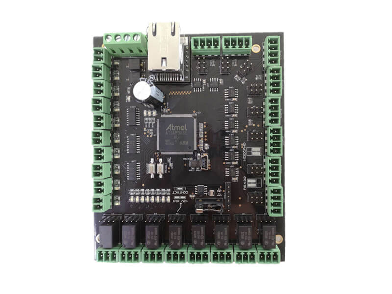
A rigid board is built on a glass reinforced epoxy core and holds its shape through assembly, test and use. A flexible circuit is built on a thin polymer film, usually polyimide, and is expected to bend, fold or twist. The rigid board provides mechanical support for its own components, while the flex circuit usually needs support added where components are placed.
That single difference propagates through the entire flow. Panel handling, stencil support, placement fixturing, reflow support and final packing all change. A production line that runs rigid boards well may need new carriers and new process settings before it can run flex reliably, which is a planning cost that belongs in the decision rather than in a surprise invoice.
Materials and the Polyimide Substrate
Rigid boards use FR-4 or a higher performance laminate, with copper weights from half an ounce upward and thicknesses measured in tenths of a millimeter per layer. Flexible circuits use a polyimide substrate, typically 12 to 50 micrometers thick, bonded to rolled annealed copper that tolerates bending far better than electrodeposited foil.
The polyimide substrate also tolerates higher temperatures, which is why flex is often chosen for tight spaces near heat sources. Its coefficient of expansion differs from that of the copper, however, and repeated thermal cycling stresses the adhesive interfaces. Material selection should account for both the mechanical duty cycle and the thermal environment, not just the electrical requirements, and the same reasoning applies to PCB dimensional stability and expansion on rigid constructions.
Bend Radius and Mechanical Limits
Bend radius is the parameter that decides whether a flex design survives. As a rule, a static bend should have a radius of at least ten times the total thickness of the circuit, and a dynamic bend that flexes repeatedly should use twenty times or more. Placing conductors on the neutral axis by using a symmetric construction dramatically improves fatigue life.
Copper orientation matters too. Rolled annealed copper bends without cracking where electrodeposited copper develops microcracks after repeated flexing. Keep conductors perpendicular to the bend line where possible, avoid plated through holes inside the bend area, and use a generous radius rather than the tightest radius the drawing allows. Every one of these choices is cheaper than a field failure.
Stiffeners and Rigid Flex Construction
A stiffener is a local reinforcement bonded to a flexible circuit so that components can be mounted, connectors inserted or screws tightened without deforming the film. Common materials include FR-4, polyimide and stainless steel, and the choice affects both stiffness and thermal expansion. Specify the stiffener material, thickness and bond area on the fabrication drawing, keep the outline consistent with board outline and mounting design rules, since a generic note invites whatever the plant has in stock.
Rigid flex combines both technologies in one construction: rigid sections carry the dense circuitry and the components, while flexible sections route between them. It removes connectors and cables, which improves reliability, but the lamination cycle is more complex and the yield is lower. Reserve rigid flex for products where the space saving or the reliability gain clearly justifies the cost.
Assembly Handling Differences
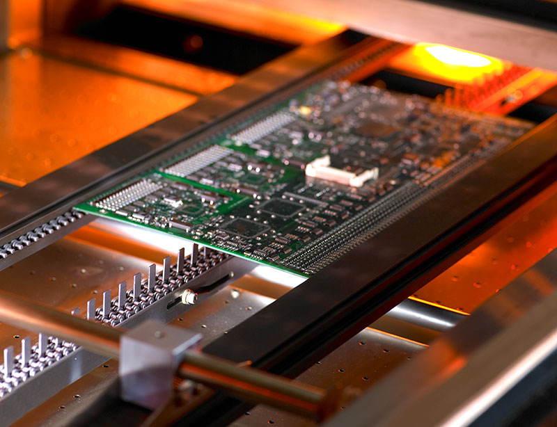
Flexible circuits arrive on panels or in carriers because they cannot support themselves through a printer or a placement machine. Paste printing needs a flat, supported surface, and reflow needs fixtures that keep the part flat without clamping it so hard that it distorts. Depaneling also differs: flex is usually cut or punched rather than routed, and the tooling must not leave burrs near conductors.
Static control deserves attention in both cases, but flex is more vulnerable because the film holds charge and the conductors are thin. Use ionizers and grounded fixtures, and keep the parts in antistatic packaging between process steps. Anecdotal damage from handling rarely appears immediately; it appears as an intermittent open after the product has been in service for a while.
Tooling, Panelization and Cost
Rigid boards amortize tooling across a rigid panel with standard rails, which makes high volume economical. Flexible circuits often use smaller panels with more handling steps, so the piece price stays higher even at volume. Rigid flex sits at the top of the cost curve, with the additional lamination and drilling steps reflected in both the tooling charge and the unit price.
Cost comparisons should therefore include the parts the flex design eliminates. A flexible circuit can remove a connector pair, a cable assembly and the labor to fit them, and that saving often exceeds the price difference. Panelize the flexible design with the same attention given to a rigid board, and confirm the fabricator’s standard panel size before committing to an outline.
Lead time follows a similar pattern. A rigid prototype can often be turned in days because the process is standardized, while a flexible or rigid flex build usually includes lamination and coverlay steps that are scheduled in batches. Plan the first flexible prototype with extra time, and use that first build to confirm the bend radius and the stiffener placement rather than only the electrical function.
Choosing Between Them
Choose rigid construction when the board must support heavy components, when thermal mass helps, or when the enclosure can accommodate a flat board. Choose flexible construction when the product must bend, when the available volume is very thin, or when the interconnect between two rigid areas is the reliability weak point. Rigid flex is justified when both needs appear in the same product.
In each case, decide early. Converting a rigid layout to flex after routing is not a translation: the layer count, the copper type, the stiffener placement and the bend areas all change. A short feasibility review before layout saves a complete redesign later.
Documenting for Production
Give the fabricator a drawing that states the substrate material, the copper type, the stiffener specification, the bend areas with their required radius and the coverlay openings. Include the impedance targets and the surface finish as well. A flexible circuit drawing carries more information than a rigid equivalent, and leaving any of it implicit invites a build that meets the drawing but not the product requirement, so review it against design guidelines for manufacturable boards before release.
gopcb produces rigid, flexible and rigid flex boards and can review the construction before the design is released. Because the same team sees the layout, the stackup and the assembly plan, the recommendation usually covers the whole path from panel to finished product rather than a single process step.
FAQ
Can a rigid board be replaced by a flex circuit to save space? Only when the mechanical structure supports it. Flex saves volume but needs stiffeners wherever components or connectors are mounted, and those stiffeners consume some of the space that the flex construction was meant to save.
How many flex cycles can a flexible circuit survive? It depends on the radius and the construction. A well designed dynamic bend with a generous radius and rolled annealed copper can survive hundreds of thousands of cycles, while a tight bend with plated holes may fail in a few thousand.
Is rigid flex worth the cost for a small product? It is worth it when the flexible section replaces a connector pair that would otherwise be the least reliable joint in the product. If the interconnect is short and static, a rigid board with a cable is usually the better economic choice.