FR4 vs Rogers PCB for RF Modules – Which Material Is Better for Your RF Product?
With the rapid development of wireless technologies such as 5G, Wi-Fi 6/7, Bluetooth, LoRa, Zigbee, GPS, automotive millimeter-wave radar, and satellite communications, RF modules demand increasingly stringent PCB materials.
For RF module design, the PCB is not just a carrier for circuits; it directly impacts signal integrity, impedance control, insertion loss, antenna efficiency, and overall system communication performance.
The two most common types of RF PCB materials on the market are FR4 and Rogers high-frequency laminates. What are the key differences? How should you choose for different frequency bands and products? This article provides a comprehensive analysis from the perspectives of material properties, cost, manufacturing processes, and application scenarios to help engineers and procurement professionals make informed decisions.
1. Quick Comparison: FR4 vs Rogers PCB
The primary difference lies in high-frequency signal transmission capability. Here is a quick comparison:
- Material Cost: FR4 (low) vs Rogers (higher)
- High-Frequency Performance: FR4 (moderate) vs Rogers (excellent)
- Dissipation Factor (Df): FR4 (0.015–0.025) vs Rogers (0.001–0.004)
- Signal Integrity: FR4 (moderate) vs Rogers (excellent)
- Impedance Control Stability: FR4 (moderate) vs Rogers (excellent)
- Thermal Stability: FR4 (good) vs Rogers (better)
- Manufacturing Difficulty: FR4 (lower) vs Rogers (higher)
- Recommended Frequency: FR4 (below 2–3 GHz) vs Rogers (above 3 GHz, even millimeter-wave)
In summary, if cost control is the priority, FR4 remains the mainstream choice; if wireless performance and high-speed transmission are critical, Rogers PCB holds a clear advantage.
2. Dielectric Loss (Df) – The Key Parameter for RF Performance
For RF modules, lower dielectric loss (loss tangent, Df) means less high-frequency signal attenuation.
Typical Df values for common PCB materials:
- Standard FR4: 0.018–0.025
- High-speed FR4: 0.010–0.015
- Rogers RO4003C: 0.0027
- Rogers RO4350B: 0.0037
Due to its extremely low Df, Rogers materials deliver benefits such as lower insertion loss, higher antenna radiation efficiency, longer communication range, better transmit power utilization, more stable receiver sensitivity, and improved high-frequency link consistency. This makes Rogers PCB the industry standard for frequencies above 5 GHz and especially for millimeter-wave bands.

3. Frequency Range Suitability
Different wireless products impose varying requirements on PCB materials.
FR4 is suitable for: 433 MHz, 470 MHz, 868 MHz LoRa, 915 MHz IoT, basic Bluetooth, smart home controllers, consumer electronics – generally for frequencies below 2 GHz, FR4 is adequate.
Rogers is preferred for: 2.4 GHz Wi-Fi, Wi-Fi 6/7, 5 GHz Wi-Fi, 5.8 GHz video transmission, high-precision BeiDou/GPS, automotive 24 GHz radar, 77 GHz millimeter-wave radar, 28/39 GHz 5G mmWave, satellite communications. As frequency increases, FR4 loss rises rapidly while Rogers maintains excellent transmission performance.
4. Impedance Control Capability
For RF PCBs, 50Ω impedance control is fundamental. Rogers materials offer tighter impedance tolerance (±5% or better) compared to FR4 (±10% typically), owing to more stable dielectric constant (Dk) over temperature and frequency. Therefore, Rogers is often used in high-gain antennas, power amplifiers (PA), low-noise amplifiers (LNA), RF front-end modules, high-frequency filters, and microwave communication equipment.
5. Cost Comparison – Why FR4 Still Dominates
Despite Rogers’ superior performance, FR4 holds the majority market share due to cost advantages. For a 100×80 mm 4-layer RF PCB, approximate costs:
- FR4: Prototype (5 pcs) $25–60; Volume (1000 pcs) $1.5–4/pcs
- Rogers RO4350B: Prototype $120–350; Volume $8–20/pcs
Overall, Rogers material costs 3–8 times that of FR4, with higher processing costs and longer lead times. For cost-sensitive products, FR4 remains the more economical choice.
6. Thermal Performance and Reliability
RF modules generate significant heat from power amplifiers, transceivers, and power devices. Compared to FR4, Rogers PCB offers lower CTE, better dimensional stability, higher thermal cycling resistance, and superior long-term reliability. This is especially important in automotive, aerospace, industrial communication, and outdoor wireless equipment, where Rogers reduces solder joint fatigue and performance drift due to thermal stress.
7. Recommended PCB Material for Different RF Modules
- LoRa (433/868/915 MHz) – FR4
- BLE – FR4 or Rogers
- Zigbee – FR4
- Wi-Fi 2.4 GHz – Rogers preferred
- Wi-Fi 5 GHz – Rogers
- Video transmission – Rogers
- High-precision GPS – Rogers
- Automotive mmWave radar – Rogers
- 5G mmWave – Rogers
Higher frequency demands superior PCB material performance.
8. Hybrid PCB – The Best Balance of Performance and Cost
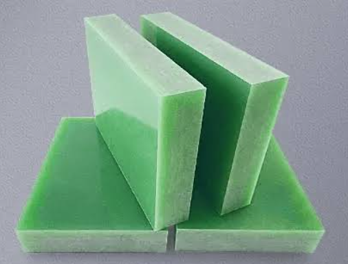
An increasing number of high-end RF products adopt FR4+Rogers hybrid PCBs. A typical stack-up uses Rogers RO4350B on the top layer (for RF traces and antenna), FR4 in the middle layers (for digital, power, and control), and Rogers on the bottom for a stable RF return path. This hybrid design offers:
- Excellent high-frequency performance
- 30–50% material cost savings compared to all-Rogers
- Supports mixed high-speed digital and RF designs
- Widely used in 5G, Wi-Fi modules, automotive radar, and satellite communications
Hybrid PCBs have become a mainstream solution for modern wireless communication products.
9. How to Choose the Right PCB Material for Your RF Module
Choose FR4 if: operating frequency < 2 GHz, cost-sensitive consumer product, low signal loss requirements, high-volume production, applications like smart home, IoT terminals, basic wireless modules.
Choose Rogers if: frequency > 2.4 GHz, strict requirements for insertion loss and signal integrity, antenna performance critical, high-precision impedance control needed, applications like 5G, mmWave radar, satellite communications, high-speed wireless networks.
10. Why More Companies Choose gopcb for RF Module PCB Manufacturing
As a professional PCB manufacturer, gopcb has extensive experience in high-frequency PCB production, offering solutions including FR4, high Tg FR4, Rogers, Taconic, Isola, PTFE, and FR4+Rogers hybrid PCBs. Our core strengths:
- 2–40 layer high-frequency PCB capabilities
- High-precision 50Ω/90Ω/100Ω impedance control
- Long-term stock of Rogers, Taconic, and other premium materials
- Support for hybrid, multilayer, and HDI high-frequency boards
- IPC Class 2/Class 3 compliance
- Full turnkey services from PCB fabrication to SMT assembly and PCBA
- Quick-turn prototyping and volume production with global delivery
Whether you are developing Wi-Fi modules, Bluetooth, LoRa, 5G infrastructure, automotive radar, or satellite communication equipment, gopcb provides stable, high-performance RF module PCB manufacturing services. Explore our PCB manufacturing and SMT PCB assembly capabilities, along with turnkey PCB assembly for complete solutions.
11. Conclusion
FR4 and Rogers PCBs are not inherently superior to each other; they serve different application scenarios. If cost and lower frequencies are your priorities, FR4 is a proven, reliable choice. If your product operates above 2.4 GHz and demands high signal integrity, low loss, and precise impedance control, Rogers PCB is undoubtedly the better fit. For many modern wireless products, FR4+Rogers hybrid PCBs offer an optimal balance of performance and cost, making them the mainstream design choice for Wi-Fi, 5G, automotive radar, and high-end IoT devices.
For professional assistance in material selection and manufacturing, consider gopcb’s prototype PCB assembly and high-volume PCB assembly services to bring your RF products to market efficiently.