
Gaming Mouse PCB: Sensor, Latency and Rigid-Flex Layout
A gaming mouse PCB is a small board with an unusually demanding specification. It has to report movement with almost no delay, survive being clicked millions of times, run for weeks on a charge, and do all of it inside a shell that the user holds in one hand. The board inside is a dense mixed signal design where a fast digital bus, an optical sensor and a radio share a few square centimetres.
What the Board Controls
The microcontroller reads the optical sensor, scans the buttons and the wheel encoder, controls the lighting and talks to the host through either a cable or a radio. Each of those functions has its own timing requirement, and the design is judged by the total delay from a physical movement to the report that reaches the computer.
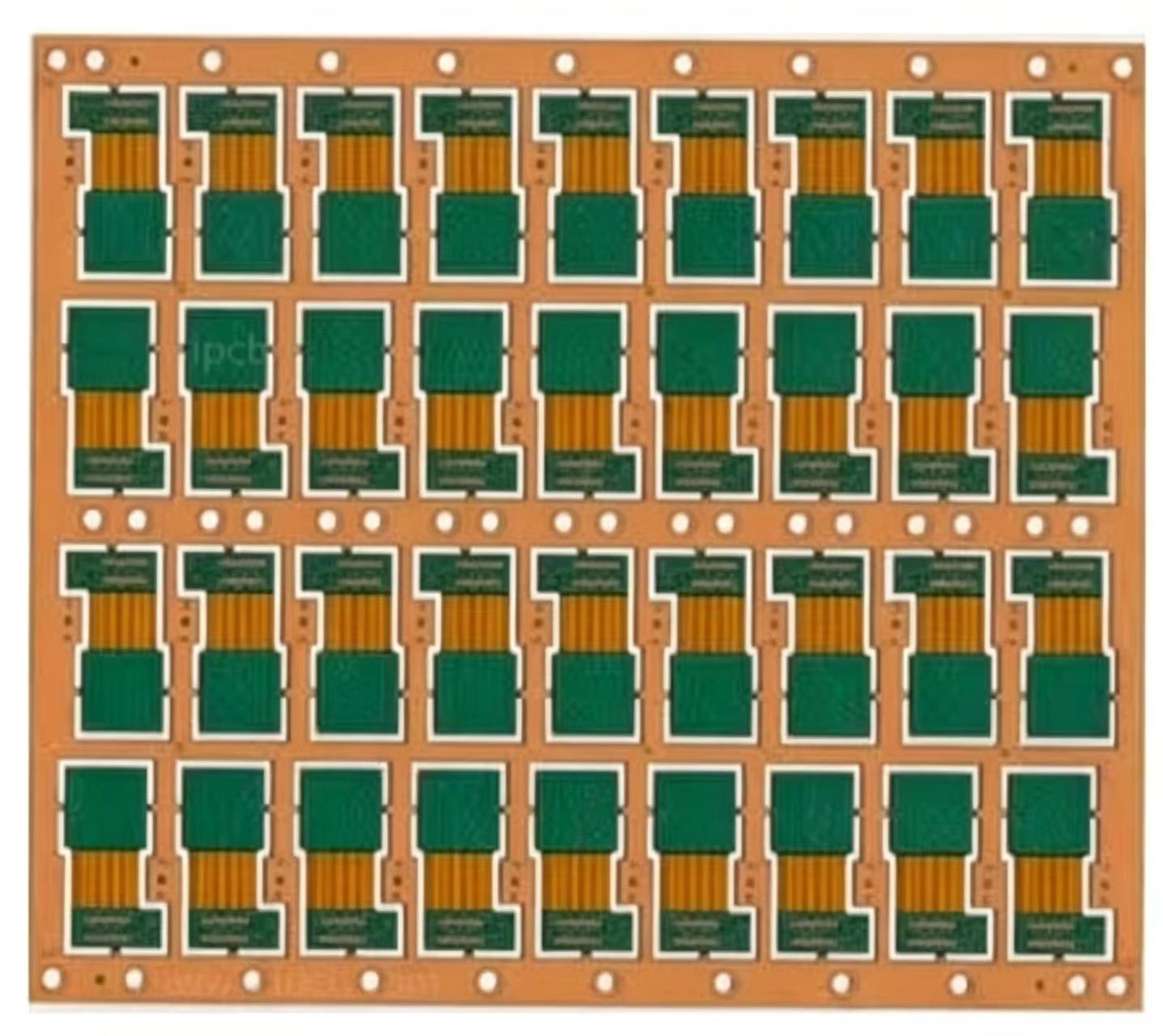
The mechanical arrangement drives the layout. The sensor must sit under the optical opening at the exact height and angle the datasheet requires, the switches are positioned by the shell, and the battery occupies whatever volume is left. The board is often split into a main section and a small section for the buttons, connected by a flexible section rather than a cable.
The Sensor and Its Interface
The optical sensor is a small camera running at several thousand frames per second, and it communicates over a serial interface at tens of megahertz. Its supply and its reference both matter: noise on the sensor supply appears as jitter in the reported movement, and a reference that shifts with the load changes the sensor’s behaviour.

The interface signals should be routed as short as possible with a continuous reference beneath them, and kept away from the lighting circuits, which switch at high current. Decoupling belongs at the sensor rather than at the regulator, and the ground the sensor uses should be the same one the microcontroller uses for the interface. The routing rules for short fast buses are described in high frequency trace and data bus routing.
Latency
Latency accumulates from several places. The sensor integrates each frame for a fixed period, the microcontroller processes and queues the report, and the interface transmits it. Of those, only the last is much affected by the board, and it is affected through the integrity of the link rather than through its speed.
What the board can do is avoid retries. A radio link that has to retransmit because of a corrupted packet has a far greater effect on the reported delay than any amount of layout optimisation elsewhere, and the same applies to a USB connection. Keeping the radio’s supply clean and its antenna clear is therefore a latency measure as much as a range measure.
Buttons, Encoders and Debounce
The switches are mechanical and they bounce. Debouncing is normally done in firmware, but the electrical arrangement still matters: a switch connected to a pin with a long trace and a weak pull-up will pick up noise, and a trace that runs beside the lighting circuit will couple the switching edges of the light emitting diodes into the button input.
The encoder on the wheel produces two quadrature signals at a low frequency, but its edges are fast and its contacts are mechanical. Series resistance and a capacitor at the input reduce the effect of contact bounce and of the cable, and the two channels should be routed together so that they see the same noise environment, because the direction is deduced from which channel changes first.
Wireless, Battery and Charging
A wireless mouse adds a radio, a battery and a charging circuit to an already dense board. The radio needs a clean supply, a ground plane beneath it and a defined antenna area, and the transmitter draws a pulse of current that must not disturb the sensor.
The charging circuit and its connector introduce a path from the outside world into the product, and it should be protected and separated from the analogue and radio sections. The traces that carry the charging current and the battery current must be sized for the current they carry and for the temperature rise the shell allows, following the same rules as any other power path, as described in trace width and current calculation.
Rigid-Flex and Mechanical Layout
Folding the board makes the product thinner and allows the buttons to be placed where the hand expects them, but it brings requirements of its own. The bend radius must be large enough relative to the flexible section thickness, the copper in the bend should be kept thin and placed near the neutral axis, and no plated hole should sit in the folding region.
The shape also determines how the board is located in the shell. Mounting features should be designed so that the board cannot move under a click, because a board that shifts changes the height of the sensor above the surface and the feel of the buttons. The principles that govern the outline and the mounting are described in board outline and mounting design.
Lighting Noise and How to Contain It
The lighting is the largest current consumer after the radio and the largest source of interference on the board. Each light emitting diode is driven by a switching regulator or a constant current source whose inductor and switch node radiate, and the resulting noise can be picked up by the sensor interface, by the button inputs and by the radio.
The cure is placement and layout rather than filtering. Keep the drivers and their inductors in one region, keep the loop between the input capacitor, the switch and the inductor as small as possible, and route the sensor and radio circuits in another region with their own return paths. The general techniques are described in EMI suppression design principles.
Test and Yield
The board is dense and assembled at high volume, so the design has to be testable. Test points for the sensor interface and the radio are useful at the prototype stage but cost area in production, so the final design usually relies on functional test of the assembled unit together with the inspection of the fine pitch joints.
Yield is dominated by the smallest features: the sensor’s land pattern, the microcontroller’s pitch and any via in pad in the assembly area. Designing to the fabricator’s demonstrated capability rather than to a general rule is what keeps the yield predictable, and it matters more on a product where the board is a small fraction of the finished cost. A reliable assembly process is worth more than a marginal reduction in board area, because the cost of a reworked unit exceeds the saving on the laminate.
FAQ
Does the board affect the click latency? Only indirectly. The link quality matters most, because a retransmission costs far more delay than the layout itself.
Why is rigid-flex used in a mouse? To place the buttons and the sensor where the mechanical design needs them while keeping the assembly thin and reducing the number of connectors.
Can the sensor and the radio share a supply? They can share a rail, but each needs its own local decoupling and a return path that does not carry the other’s current.