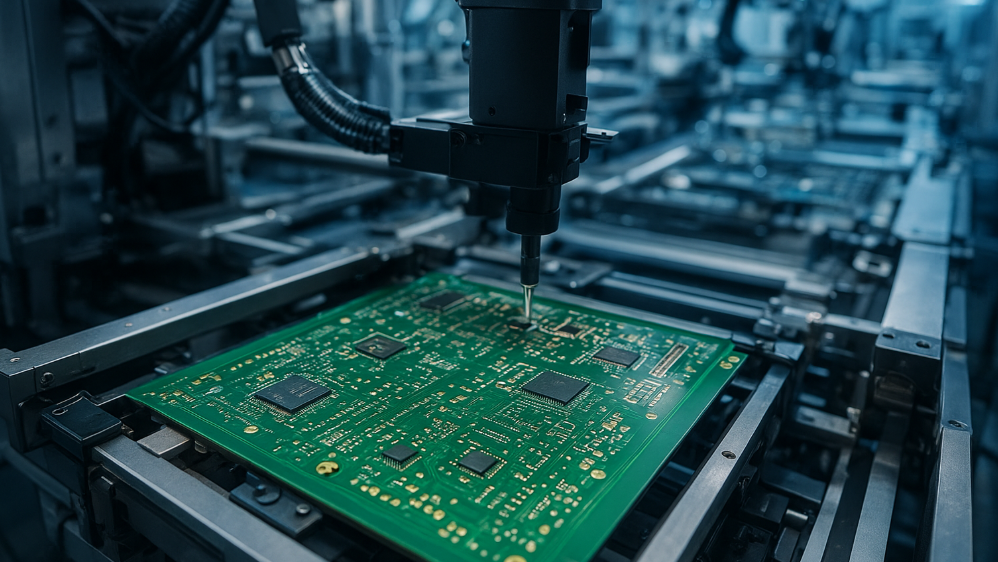
Gate Driver Layout for Silicon Carbide and GaN Stages
Silicon carbide and gallium nitride devices switch in a few nanoseconds, and that speed is the point of using them. It also means that every nanohenry of inductance in the gate driver path produces a voltage spike that can exceed the gate rating, turn the device on when it should be off, or ring well beyond the intended switching frequency. The layout of the gate loop is therefore a functional part of the circuit rather than a detail.
Why Wide Bandgap Devices Change the Layout
A silicon device with a switching time of twenty nanoseconds tolerates a gate loop with a few nanohenries because the resulting voltage error is small. A silicon carbide or gallium nitride device with a switching time of two nanoseconds sees ten times the voltage for the same inductance, and its threshold voltage is often lower. The combination makes a layout that was acceptable for a silicon design a source of failures for a wide bandgap one.
The drain voltage slew rate is the other factor. A fast dv/dt drives current through the parasitic capacitances of the circuit, including the gate to drain capacitance, and that current flows in the gate circuit whether the designer intended it or not. The result is a turn-on transient on a device that is supposed to be off, and the only practical defence is to lower the impedance of the gate loop.
The Gate Loop and Its Inductance
The gate loop is the path from the driver output, through the gate resistor, to the gate, and back from the source to the driver ground. Its inductance is set by the physical area enclosed by that path, so the layout rule is simple: minimise the area. A driver placed a few millimetres from the device with the return path directly beneath the gate trace has a far lower loop inductance than one placed a centimetre away with the return routed around the device.
Where the loop cannot be made short, the gate resistor is the main damping element. A larger resistance reduces the ringing but slows the switching, which increases switching loss. The trade-off is fundamental, and the layout should be arranged so that the resistance needed for stability is as small as possible, which means minimising inductance first and choosing the resistor afterwards.
Common Source Inductance
Common source inductance is the inductance shared between the gate drive path and the power path. Any voltage developed across it by the drain current appears in the gate loop as a feedback signal, and it slows the switching and can cause oscillation. The cure is a Kelvin connection: a separate source connection for the gate return, taken directly from the device source pad rather than from the power source node.
Kelvin connections require a device package that provides them, or careful layout of a package with multiple source pins. Where the package allows it, the gate return should use a source pin that carries no power current, and the power path should use the remaining pins. This is one of the reasons that modern power packages have separate pins for the drive and the power connections, and ignoring them wastes the advantage.
Return Path and Isolation
An isolated gate driver adds a second consideration: the return path of the isolated supply. The secondary side of the driver needs a local ground that is robust and low impedance, and the isolation barrier must be respected by the layout. Traces must not cross the barrier, and the creepage distance that the driver package provides must not be undermined by routing on the board.
Where several devices share a driver, the layout should be a star or a bus with short spurs rather than a chain. A chain topology makes the gate loop of the last device much longer than that of the first, and the asymmetry shows up as different switching behaviour between the two positions, which is difficult to diagnose.
Thermal and Space Constraints
A gate driver that must sit close to the device competes for space with the thermal copper that the device needs. The conflict is resolved by using the inner layers for the power path and the top layer for the gate loop, or by placing the driver on the opposite side of the board directly beneath the device. A driver under the device gives an extremely short gate loop and keeps the thermal copper on the top layer intact.
Splitting the thermal path across layers is the other option. Multiple vias under the device transfer heat to inner copper while the top layer carries the gate connection. The vias must be placed so that they do not interrupt the return path of the gate loop, since a via in the wrong place forces the return current to divert and increases the loop area.
Measurement and Verification
A gate waveform measured with a probe that has a long ground lead will show ringing that does not exist. The measurement should use a tip and barrel contact at the device pins, and the gate and source should be probed differentially where possible. Without that discipline, the designer spends time damping a waveform that is an artefact of the probe.
The double pulse test is the standard way to characterise a power stage. It applies a single pulse and then a second pulse of known duration, allowing the switching energy to be measured and the ringing to be observed at a controlled current. Comparing several layouts under the same test conditions shows directly how much the gate loop inductance costs in switching loss, and the suppression measures that follow are easier to justify with that evidence.
Practical Layout Rules
Several rules are worth repeating. Keep the driver as close to the device as the thermal design allows, and place the gate resistor next to the driver rather than next to the gate so that the resistor body does not add length to the loop. Route the gate trace over a continuous reference, and keep the reference connected to the driver ground at one point rather than in a loop.
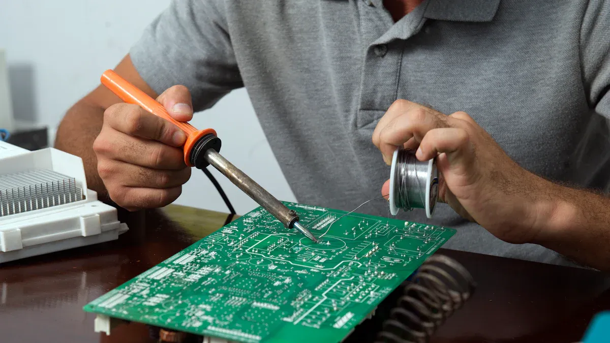
Avoid vias in the gate trace unless they are unavoidable, and where they are needed, place them in pairs so that the return current can follow. Keep the gate trace away from the switching node, since the dv/dt there couples into the gate through the trace capacitance. The same care applies on prototype builds, where a hand assembled board often has a longer gate loop than the eventual layout. Finally, review the layout with the device manufacturer reference design as a comparison, because the recommended layout embodies the measurements that the manufacturer made on its own evaluation board.
Documentation is the last element. The gate loop layout, the resistor value, and the measured switching waveform belong with the schematic, because a later revision that moves the driver a few millimetres can undo the work without any obvious change to the circuit. Where several power stages share a board, each should be documented and measured in the same way so that the results can be compared.
FAQ
How close must the gate driver be to the device? As close as the thermal layout permits, typically within a few millimetres. A driver mounted directly beneath the device on the opposite layer gives the shortest loop of all.
What is a Kelvin source connection? A separate source return for the gate circuit, taken directly from the device source pad so that it carries no power current. It removes the common source inductance that otherwise slows switching and causes oscillation.
Why does my gate waveform ring so much? Usually gate loop inductance combined with a fast switching device. Check the loop area first, then the probe technique, and only then increase the gate resistance, which trades efficiency for damping.