High Frequency PCB Price: What Drives the Cost
A high frequency PCB costs more than an ordinary board for reasons that are easy to state and harder to quantify: the laminate is expensive, the geometry has to be controlled tightly, and the test programme is heavier. What buyers usually lack is a breakdown that separates unavoidable material cost from process adders that can be designed out. This article sets out the numbers behind each line so a budget can be built before the stackup is fixed.
Laminate Cost Is the Floor
The base material sets the minimum price of the board. Standard FR-4 runs about 0.20 to 0.60 dollars per square foot, while a ceramic filled hydrocarbon material such as RO4003C sits between 1.80 and 3.50 dollars and RO4350B between 2.50 and 5.00 dollars. PTFE based laminates reach 5.00 to 8.00 dollars per square foot, and alternatives such as Taconic RF-35 fall between 3.00 and 6.00 dollars.
That spread means material selection drives the final price more than any other single decision. Where the design does not need the lowest possible loss, stepping down from a PTFE laminate to a hydrocarbon material can save 15 to 20 percent without changing the layer count or the fabrication process, and it usually shortens the lead time as well.
Layer Count and Stackup Structure
Layer count multiplies everything above. A two layer RO4350B board of 100 by 100 mm in a fifty piece batch typically quotes 85 to 120 dollars per unit. A four layer construction that mixes PTFE with FR-4 in the same stackup runs 180 to 300 dollars per unit at twenty pieces, and a six layer all PTFE board reaches 250 to 400 dollars. A hybrid stackup keeps the low loss laminate on the signal layers and uses ordinary FR-4 elsewhere, which is the cheapest way to reach a given electrical performance.
Structure adds more. Blind vias, buried vias and embedded microstrip constructions can add over 30 percent, because each one introduces an additional lamination cycle and more yield risk. Stackup rules that keep these features to a minimum while still meeting the electrical target are described in layer stackup for one to eight layers, and they apply with more force here because the material is expensive enough that scrap hurts.
Thickness, Copper and Dimensions
Board thickness above 2.4 mm raises the overall price by 10 to 20 percent because of extra material and longer drilling cycles. Moving from one ounce to two ounce copper adds roughly 10 to 15 dollars per board, and it is worth doing only where the current or the conductor loss requires it, since heavy copper also complicates the etch tolerance that fine geometry already strains.
Board size interacts with panel utilisation. A high frequency design that does not nest well on the standard panel wastes expensive laminate, and that waste is charged to the order. Adjusting an outline slightly, or accepting a common panel size, often saves more than a material substitution, which is why fabricators ask about panel fit before they quote.
Impedance Tolerance and Test
Impedance tolerance is priced separately because it changes both engineering effort and yield. Time domain reflectometry testing of impedance coupons runs about 80 to 150 dollars per batch. A tolerance of plus or minus ten percent is usually included in the base price, while tightening it to plus or minus five percent adds 15 to 30 dollars per board and increases the risk of scrap.
The tolerance also constrains the design. Tighter control means narrower process windows on dielectric thickness, copper thickness and etch, and it limits which laminates can be used at all. Where the high frequency traces run short enough that a ten percent variation is tolerable at the receiver, specifying five percent just adds cost.
Surface Finish and Microvias
Finishes behave differently at high frequency because skin effect concentrates current near the surface. Hot air solder levelling is the cheapest option and the least suitable for high frequency work. Electroless nickel immersion gold adds 20 to 30 dollars per board and gives a flat, stable pad. Immersion silver adds 15 to 25 dollars and performs well electrically, while ENEPIG adds 30 to 50 dollars and is chosen when gold wire bonding is involved.
Microvia technology is billed per hole rather than per board. Laser drilled microvias add 0.03 to 0.10 dollars each, buried and blind via constructions with plugging add 10 to 20 dollars per board, and back drilling carries a set up charge per batch. These adders are cumulative, so a design that uses microvias where a through via would work pays for them twice, once in cost and once in yield.
Putting a Quotation Together
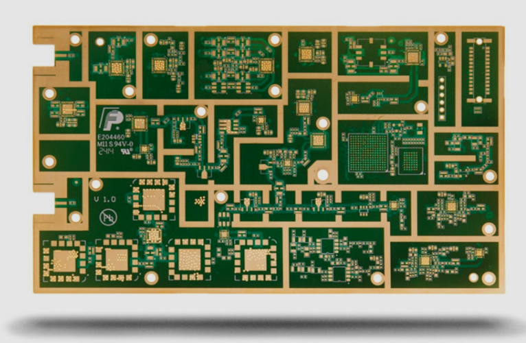
A realistic total for a four layer impedance controlled board with a hybrid stackup, five percent tolerance and ENIG finish lands well inside the 180 to 300 dollar range for a small batch, and falls rapidly with volume as tooling and engineering are amortised. The prototype premium is largely engineering and test rather than material, which is why the second build of the same design costs noticeably less than the first.
Electromagnetic behaviour deserves a line in the engineering budget as well, since shielding and partitioning decisions made late are expensive to correct. The principles in EMI suppression design principles are cheaper to apply during layout than after a failed compliance test, and on high frequency material the penalties for a late change are higher because every revision consumes expensive laminate.
Reducing Cost Without Losing Performance
Four decisions carry most of the savings. Choose the lowest loss laminate that still meets the loss budget rather than the best available. Keep the low loss material on the signal layers only. Relax impedance tolerance to ten percent where the channel allows it. And simplify the via structure, replacing microvias with through vias wherever the stub effect is acceptable.
A fabrication partner such as gopcb can model these options against the link budget and report which combination still passes with margin. That analysis happens before tooling, when changes are free, rather than after the first build when every revision costs material, engineering time and a delay to the program schedule.
Volume and Lead Time
Volume and lead time are the last two variables in the equation. A fifty piece batch of a four layer high frequency board may quote at 85 to 120 dollars per unit, while a five hundred piece run of the same design can fall by more than half once tooling is amortised and the process has stabilised. Lead time moves the other way: expedited builds on these materials usually require special handling, so rush charges of twenty to fifty percent are normal. Planning the production build around the laminate lead time, rather than the other way round, avoids most of that premium.
FAQ
Why is a high frequency PCB so much more expensive than FR-4? The low loss laminate costs several times more per square foot, the process windows are tighter, and the test programme including impedance coupons is heavier than on an ordinary board.
Does tighter impedance tolerance always improve performance? No. It improves consistency, but if the channel tolerates a ten percent variation, specifying five percent adds cost and yield risk without a measurable benefit.
Can a hybrid stackup really save money? Yes. Confining the low loss laminate to the signal layers typically saves 15 to 25 percent of material cost while keeping the electrical performance of the RF nets intact.