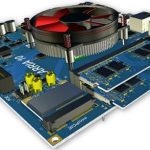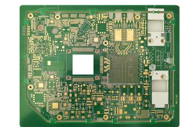
In the early stages of PCB Design, engineers were often less involved in planning the internal layer structure of a circuit board. Designers mainly needed to know the required number of layers and basic layer assignments to configure their design tools. Beyond that, they had limited interaction with the layer stackup process.
This was mainly because:
- PCB performance requirements were not as demanding as they are today.
- Manufacturing data requirements were relatively simple.
- Earlier PCB design software lacked advanced PCB Layer Stackup planning and configuration capabilities.
With the rapid development of high-speed electronics, this situation has changed significantly. Modern PCB Layout engineers must carefully define and optimize the layer structure to ensure electrical performance, manufacturability, and reliability.
Today, advanced PCB design platforms provide powerful stackup management features, allowing designers to define dielectric materials, copper thickness, impedance requirements, and layer configurations. However, designers still need a strong understanding of materials, signal behavior, and manufacturing processes to create an effective stackup.
For professional PCB solutions, Kingda provides comprehensive PCB manufacturing support, helping customers achieve optimized stackup structures for different applications, including high-speed, high-density, and multilayer circuit boards.
The Relationship Between PCB Layer Count and Circuit Complexity
The number of layers in a PCB is closely related to the number of signals that need to be routed. As electronic products become smaller and more powerful, the complexity of circuits continues to increase.
Modern designs typically include:
- More components and higher pin-count devices.
- Increased routing density.
- More high-speed signal networks.
- Greater power distribution requirements.
When circuit complexity increases, designers generally have two choices:
- Reduce trace width and spacing.
- Increase the number of PCB layers.
However, reducing trace width beyond manufacturing capability can affect reliability and increase production risks. Therefore, adding additional layers is often the preferred solution for advanced applications.
Although many traditional designs could previously be completed with four or six layers, today’s high-performance applications may require eight or more layers to achieve proper electrical performance.
Additional layers provide advantages such as:
- Dedicated signal routing areas.
- Improved Impedance Control.
- Better separation between high-speed signals and sensitive circuits.
- Additional power and ground planes.
- Improved signal return paths.
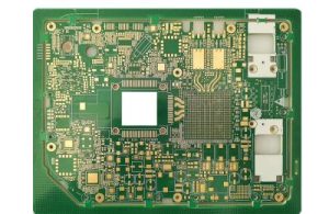
Key Factors Affecting PCB Stackup Design
Creating an optimized PCB Layer Stackup requires consideration of multiple technical factors.
1. Signal Integrity Requirements
For high-speed designs, maintaining Signal Integrity is critical. Improper layer arrangement can cause problems such as:
- Signal reflection.
- Crosstalk.
- Electromagnetic interference.
- Excessive signal loss.
A well-designed stackup ensures that high-speed signals have controlled impedance reference planes and stable return paths.
2. Impedance Control
As signal speeds increase, trace impedance becomes an essential design parameter. The dielectric thickness, copper thickness, and material characteristics directly affect impedance values.
Therefore, designers must carefully select:
- PCB material.
- Dielectric thickness.
- Copper foil thickness.
- Trace width and spacing.
Proper Impedance Control helps maintain signal quality and improves overall system reliability.
3. Power and Ground Plane Configuration
Modern electronic systems often require multiple power domains and ground networks. Additional plane layers help:
- Reduce power noise.
- Improve current distribution.
- Provide better electromagnetic shielding.
- Support high-speed signal performance.
Advanced Materials and Their Impact on PCB Stackup Design
As PCB technology advances, traditional FR-4 materials may no longer meet all application requirements.
High-performance applications such as:
- 5G communication equipment.
- Automotive electronics.
- Medical devices.
- High-speed computing systems.
may require specialized materials with improved electrical and thermal characteristics.
Different PCB materials can significantly affect transmission line performance. Changes in:
- Dielectric constant (Dk).
- Dissipation factor (Df).
- Thermal stability.
- Moisture resistance.
can influence the final performance of the circuit board.
Therefore, selecting the correct material is an important part of PCB Manufacturing and stackup planning.
Challenges Faced by Modern PCB Layout Engineers
Today’s PCB designers face many challenges that previous generations of engineers rarely encountered.
Tight Development Schedules
The demand for faster product launches continues to increase. Companies must respond quickly to market competition while maintaining product quality.
For industries such as medical electronics, automotive systems, and communication equipment, PCB development cycles are becoming increasingly demanding.
Design engineers must complete complex PCB Layout tasks quickly while ensuring:
- Correct layer configuration.
- Manufacturing feasibility.
- Stable electrical performance.
Increasing Design Complexity
Modern circuit boards require designers to consider many additional factors, including:
- High-speed routing.
- Differential pair design.
- Power integrity.
- Thermal management.
- EMI control.
Without proper stackup planning, even a correctly designed schematic may fail to achieve the required performance.
Limitations of PCB Design Tools
Although modern PCB CAD software provides advanced features, not every tool offers the same level of stackup management capability.
An effective PCB design platform should allow engineers to:
- Create customized layer structures.
- Define dielectric materials.
- Configure copper thickness.
- Perform impedance calculations.
- Verify manufacturing requirements.
These functions significantly improve design efficiency and reduce production risks.
How PCB Design Software Helps Optimize Layer Stackup
Modern PCB CAD tools provide various features to simplify stackup creation and management.
A good design environment allows engineers to:
- Automatically generate standard stackup structures.
- Customize signal, power, and ground layers.
- Define material properties.
- Set manufacturing tolerances.
- Validate impedance requirements.
However, software alone cannot replace manufacturing expertise.
Designers still need practical knowledge of PCB production processes, material behavior, and supplier capabilities.
Working with PCB Manufacturers for Better Stackup Design
Collaboration between PCB designers and manufacturers is essential for successful PCB Manufacturing.
Experienced manufacturers can provide valuable guidance regarding:
- Available materials.
- Manufacturing limitations.
- Layer count optimization.
- Cost-effective solutions.
- Reliability improvements.
By involving PCB manufacturers early in the design process, engineers can avoid costly redesigns and ensure that the final board meets performance expectations.
Kingda works closely with customers during the early design stage to provide professional recommendations for PCB Layer Stackup, material selection, and manufacturing optimization. This approach helps customers achieve reliable, high-performance PCB solutions while balancing performance and cost.
Conclusion
As electronic products continue to evolve toward higher speed, smaller size, and greater integration, PCB Layer Stackup design has become a critical factor in successful PCB Design.
A properly optimized stackup can improve:
- Signal Integrity
- Impedance Control
- Power performance
- Manufacturing reliability
- Product lifespan
By combining advanced PCB design tools with professional manufacturing knowledge, designers can create high-performance circuit boards that meet the requirements of modern electronic applications.
Through close cooperation with experienced PCB manufacturers such as Kingda, engineers can develop reliable multilayer solutions while reducing design risks and improving production efficiency.