What Is IPC-A-610?
IPC-A-610, officially known as Acceptability of Electronic Assemblies, is one of the most widely recognized industry standards for evaluating the quality and acceptability of assembled electronic products. Developed by IPC, the global organization that develops standards for the electronics manufacturing industry, IPC-A-610 provides visual acceptance criteria for electronic assemblies, including PCB assembly, solder joints, component placement, board cleanliness, markings, and workmanship.
Unlike a standard that primarily defines how a product should be manufactured, IPC-A-610 focuses on what an acceptable finished electronic assembly should look like. It is therefore widely used by PCB assembly manufacturers, OEMs, EMS providers, quality engineers, inspectors, and electronics manufacturers to establish consistent quality requirements.
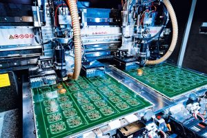
IPC-A-610 applies to a broad range of electronic assemblies, including surface-mount technology (SMT), through-hole technology (THT), mixed-technology assemblies, connectors, wires, terminals, and advanced packages such as BGA.
For manufacturers such as Kingda, applying IPC-A-610 acceptance criteria helps create a consistent quality framework throughout the PCB assembly manufacturing process, from component placement and soldering to inspection and final quality control.
It is important to note that IPC-A-610 is closely related to, but different from, other IPC standards. For example, IPC-A-600 primarily addresses the acceptability of bare printed circuit boards, while IPC J-STD-001 focuses more heavily on soldering materials, processes, and requirements. IPC-A-610 is mainly concerned with the acceptability of the completed electronic assembly.
What Are IPC-A-610 Class 1, Class 2, and Class 3?
IPC-A-610 divides electronic assemblies into three product classes according to their intended use, reliability requirements, and consequences of failure.
The three classes are not simply different levels of manufacturing quality. Instead, they represent different end-use requirements. A Class 3 product is not necessarily manufactured using completely different processes from a Class 1 product, but it is subject to more demanding acceptance criteria because its operational reliability is more critical.
IPC-A-610 Class 1
IPC-A-610 Class 1 applies primarily to general electronic products where the main requirement is that the assembly performs its basic intended function.
Typical applications include:
- Consumer electronics
- Low-cost electronic devices
- Non-critical household products
- General-purpose electronic equipment
Class 1 allows certain cosmetic or workmanship conditions that do not affect the functionality of the finished assembly. The emphasis is generally on achieving the required electrical and mechanical performance while maintaining cost-effective production.
For high-volume consumer electronics, Class 1 may be appropriate when product failure does not create significant safety or operational consequences.
IPC-A-610 Class 2
IPC-A-610 Class 2 is intended for electronic products where continued performance and extended service life are important.
Typical applications may include:
- Industrial control equipment
- Commercial electronics
- Telecommunications equipment
- Automotive electronics
- Professional electronic systems
- Instrumentation and monitoring equipment
Class 2 introduces more demanding workmanship and acceptance requirements than Class 1. Components, solder joints, conductor connections, and assembly conditions must provide a higher level of reliability for equipment expected to operate continuously or under more demanding environmental conditions.
For many industrial and commercial PCB assembly projects, Class 2 represents a practical balance between reliability, manufacturing cost, and product performance.
IPC-A-610 Class 3
IPC-A-610 Class 3 is intended for high-reliability electronic products where continuous or uninterrupted performance is essential and equipment failure may have serious consequences.
Typical applications include:
- Aerospace and aviation electronics
- Defense and military systems
- Certain medical electronics
- High-reliability telecommunications equipment
- Mission-critical industrial systems
- High-performance electronic equipment
Class 3 has the most stringent acceptance requirements of the three classes. Greater attention is given to solder joint integrity, component placement, conductor conditions, defects, and overall workmanship.
For these applications, manufacturing consistency and process control are particularly important because a small assembly defect may develop into a field failure after prolonged thermal, mechanical, electrical, or environmental stress.
IPC-A-610 Class 1 vs. Class 2 vs. Class 3
| Feature | Class 1 | Class 2 | Class 3 |
|---|---|---|---|
| Primary focus | Basic functionality | Reliable performance | High reliability |
| Typical applications | Consumer electronics | Industrial and commercial equipment | Aerospace, defense, medical, mission-critical systems |
| Acceptance requirements | Basic | More stringent | Most stringent |
| Defect tolerance | Relatively higher | Moderate | Lowest |
| Reliability requirements | Standard | High | Very high |
| Manufacturing control | Cost-effective | Controlled | Highly controlled |
Selecting the appropriate class should be based on the product’s intended application, operating environment, expected service life, reliability requirements, and potential consequences of failure.
Why Do IPC-A-610 Classes Matter?
The difference between Class 1, Class 2, and Class 3 is important because different electronic products have different reliability requirements.
A consumer device may tolerate a minor cosmetic imperfection that has no impact on functionality. However, the same condition may require additional evaluation in a high-reliability aerospace or medical application.
Therefore, manufacturers should establish the required IPC-A-610 class before production begins. This allows the PCB assembly process, inspection criteria, workmanship requirements, and quality-control procedures to be aligned with the customer’s actual application.
The selected class should also be clearly communicated through engineering documentation, purchase specifications, drawings, and manufacturing instructions.
Which IPC-A-610 Class Is Best for PCB Assembly?
There is no single IPC-A-610 class that is suitable for every PCB assembly project.
For general consumer products, Class 1 may be sufficient when the consequences of failure are limited.
For industrial, commercial, automotive, telecommunications, and professional electronic equipment, Class 2 is commonly appropriate when reliable operation and longer service life are required.
For aerospace, defense, medical, and other mission-critical applications, Class 3 may be required because reliability is a primary consideration.
The appropriate class should ultimately be determined by the product’s intended application and customer requirements rather than simply choosing the highest class for every project.
IPC-A-610 Soldering Requirements
Soldering is one of the most important aspects of electronic assembly quality. IPC-A-610 provides acceptance criteria for soldered connections used in both SMT assembly and through-hole assembly.
A reliable solder joint should provide adequate electrical conductivity and mechanical strength while meeting the applicable visual acceptance criteria.
Important factors include:
- Solder coverage
- Solder wetting
- Component alignment
- Solder joint shape
- Lead and termination conditions
- Fillet formation
- Excess solder
- Solder bridges
- Voids and other workmanship conditions
- Cleanliness and contamination
The exact acceptance criteria depend on the component type, package, termination style, assembly technology, and applicable product class.
Solder Joint Formation
A properly formed solder joint should provide a reliable connection between the component termination and the PCB land or pad.
Good solder wetting indicates that molten solder has properly bonded with the relevant surfaces. Insufficient wetting can reduce mechanical strength and electrical reliability.
For through-hole components, solder should properly interact with the component lead and plated hole structure according to the applicable acceptance criteria.
For surface-mount components, the solder joint should provide appropriate contact between the component termination and PCB pad while maintaining the required alignment and solder coverage.
Solder Fillet
A solder fillet should have an appropriate profile and provide a smooth transition between the component termination and PCB land.
Poor fillet formation can indicate problems such as insufficient solder, excessive solder, poor wetting, contamination, component misalignment, or inappropriate process parameters.
During PCB inspection, solder fillets are therefore important visual indicators of assembly quality.
Solder Joint Shape
The ideal solder joint profile depends on the package and assembly technology.
Through-hole solder joints and SMT solder joints have different geometries and acceptance criteria. A manufacturer should therefore avoid applying a single visual rule to every type of solder connection.
The solder joint must be evaluated according to the applicable IPC-A-610 criteria for the specific component and assembly technology.
Solder Cleanliness
After soldering, residues and contaminants should be evaluated according to the assembly’s cleanliness requirements.
Depending on the soldering process, flux residues may remain on the board. Some flux systems are designed to leave residues that can remain on the assembly under defined conditions, while other applications require additional cleaning.
The cleaning process should remove harmful contaminants without damaging components, solder joints, markings, or the PCB substrate.
Proper PCBA cleaning is particularly important for assemblies exposed to humidity, contamination, high voltage, or long operating periods.
Solder Joint Mechanical Strength
Solder joints must provide sufficient mechanical integrity for their intended application.
Cracks, fractures, insufficient soldering, poor wetting, or other significant defects can reduce the reliability of an assembly.
For high-reliability products, manufacturers may combine visual inspection with additional inspection and testing techniques to identify defects that cannot be reliably detected through visual examination alone.
IPC-A-610 Requirements for PCBA Cleaning and Conformal Coating
Cleaning and coating can significantly influence the long-term reliability of an electronic assembly.
However, IPC-A-610 acceptance criteria should not be interpreted as requiring every PCB assembly to be cleaned or conformally coated. The appropriate process depends on the product design, flux chemistry, environmental conditions, materials, and customer specifications.
PCBA Cleaning Requirements
The cleaning process should effectively remove harmful contaminants while protecting the PCB and components.
Common cleaning methods include:
- Manual cleaning
- Spray cleaning
- Batch cleaning
- Inline cleaning
- Aqueous cleaning
- Solvent-based cleaning
- Ultrasonic cleaning for suitable assemblies
The cleaning method should be selected according to the contamination type, component sensitivity, production volume, and reliability requirements.
After cleaning, the assembly should be properly dried to prevent moisture-related problems.
Conformal Coating Requirements
Conformal coating provides an additional protective layer over selected areas of an electronic assembly.
It may help protect the PCB assembly from:
- Moisture
- Dust
- Chemical contaminants
- Condensation
- Corrosive environments
- Certain environmental stresses
Common conformal coating technologies include acrylic, silicone, polyurethane, epoxy, and other specialized materials.
The coating material should be compatible with the PCB substrate, components, solder joints, connectors, and operating environment.
Conformal Coating Thickness
Coating thickness should be controlled according to the coating material and product specification.
A coating that is too thin may provide insufficient protection, while excessive coating can create manufacturing problems or interfere with component operation, connectors, heat dissipation, or rework.
Therefore, coating thickness should be controlled and verified using appropriate measurement methods when required.
Conformal Coating Quality
A properly applied conformal coating should provide appropriate coverage without unacceptable:
- Voids
- Bubbles
- Cracks
- Peeling
- Contamination
- Uneven coverage
- Uncoated areas where coating is required
Inspection requirements should be established according to the coating system and the product’s environmental requirements.
Component Marking and PCB Identification
Identification and traceability are essential for modern electronics manufacturing.
Appropriate markings can help manufacturers identify components, PCB revisions, production batches, and finished assemblies throughout their service life.
Component Marking
Component markings should remain sufficiently clear and durable for identification and inspection.
Depending on the application, identification may include:
- Part numbers
- Component references
- Manufacturer codes
- Revision information
- Date or lot codes
Bare PCB Marking
A bare PCB may contain identification information such as:
- PCB part number
- Revision code
- Manufacturing code
- Lot information
- Date code
- Manufacturer identification
These markings support manufacturing control and traceability.
Final Assembly Identification
A finished electronic assembly may require a unique identifier such as a serial number or production code.
This allows manufacturers to trace the assembly back to relevant production information, component batches, inspection records, and test results.
Component Position and Orientation
Clear component reference designators and polarity indicators help reduce assembly errors.
Examples include:
- Diode polarity
- Capacitor polarity
- IC pin 1 orientation
- Connector orientation
- Component reference designators
- Fiducial marks
Correct placement and orientation are especially important for complex SMT assemblies containing fine-pitch components and high-density packages.
IPC-A-610 and SMT PCB Assembly
Modern electronics increasingly rely on surface-mount technology because SMT enables compact designs, high component density, and automated production.
IPC-A-610 provides acceptance criteria relevant to SMT assemblies, including component placement and solder joint conditions.
Important SMT inspection points include:
- Component alignment
- Component orientation
- Solder coverage
- Solder bridging
- Tombstoning
- Component lifting
- Excess solder
- Insufficient solder
- Lead termination conditions
- Package-specific workmanship
For high-density assemblies, automated optical inspection (AOI) can be used to identify many visual defects efficiently.
IPC-A-610 and BGA Assembly
Ball grid array (BGA) packages are widely used in high-performance electronics because they provide a large number of electrical connections within a relatively small footprint.
However, BGA solder joints are located beneath the component package and therefore cannot normally be inspected completely using conventional visual inspection.
For this reason, manufacturers may use X-ray inspection and other appropriate inspection techniques to evaluate hidden solder connections.
Potential BGA defects include:
- Insufficient solder
- Solder bridging
- Voids
- Misalignment
- Open connections
- Abnormal solder ball formation
The inspection strategy should be selected according to package design, product class, customer requirements, and manufacturing risk.
IPC-A-610 and Automated PCB Assembly
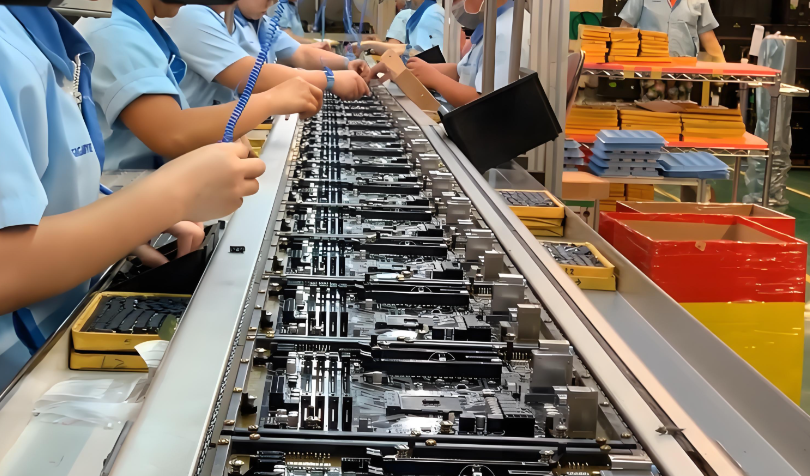
Automation plays an important role in modern PCB manufacturing and assembly.
Automated equipment can improve production consistency and reduce operator-dependent variation, but automation does not eliminate the need for process control and inspection.
Typical automated processes include:
- Solder paste printing
- SMT component placement
- Reflow soldering
- AOI inspection
- Automated X-ray inspection
- Component testing
- Functional testing
A robust manufacturing process combines equipment capability, process parameter control, inspection, and corrective action.
For example, solder paste volume, stencil condition, placement accuracy, reflow temperature profile, and inspection results should be monitored to maintain consistent assembly quality.
IPC-A-610 and Lead-Free Soldering
Lead-free soldering is widely used to meet environmental and regulatory requirements.
Compared with traditional tin-lead soldering, lead-free soldering generally requires higher process temperatures and can introduce different wetting and thermal characteristics.
IPC-A-610 provides acceptance criteria for soldered connections regardless of whether the assembly uses lead-free or tin-lead solder, while process requirements and soldering materials are addressed by other relevant standards and specifications.
Manufacturers should therefore control:
- Reflow temperature profiles
- Solder paste storage
- Stencil printing
- Component compatibility
- Thermal exposure
- Solder wetting
- Flux performance
- Inspection criteria
IPC-A-610 vs. IPC-A-600
These two standards are often confused, but they address different stages of electronics manufacturing.
IPC-A-600 focuses primarily on the acceptability of bare printed circuit boards.
It addresses conditions associated with PCB fabrication, such as:
- Conductors
- Holes
- Plating
- Solder mask
- Surface characteristics
- Lamination-related conditions
IPC-A-610, on the other hand, focuses on assembled electronic products.
It covers areas such as:
- Component placement
- Solder joints
- SMT assembly
- Through-hole assembly
- Marking
- Assembly workmanship
- Other finished assembly conditions
In a complete manufacturing process, both standards may be relevant because PCB fabrication and PCB assembly are separate manufacturing stages.
IPC-A-610 vs. IPC J-STD-001
IPC-A-610 and IPC J-STD-001 are complementary standards rather than competing standards.
IPC J-STD-001 focuses primarily on soldering processes, materials, and process requirements for producing reliable soldered assemblies.
IPC-A-610 focuses primarily on the acceptability of completed electronic assemblies through defined visual and other applicable inspection criteria.
In practical manufacturing environments, these standards can be used together.
For example, J-STD-001 can help establish how a soldering process should be controlled, while IPC-A-610 can help determine whether the resulting assembly meets the applicable acceptance criteria.
Why IPC-A-610 Matters for PCB Assembly Quality
Following IPC-A-610 helps manufacturers establish a consistent quality framework throughout the assembly process.
Key benefits include:
Improved Manufacturing Consistency
Clear acceptance criteria reduce ambiguity between manufacturers, customers, inspectors, and engineering teams.
Reduced Defect and Rework Rates
Well-defined inspection criteria can help identify defects earlier, reducing unnecessary rework and production delays.
Better Product Reliability
Proper soldering, component placement, and workmanship contribute to stronger mechanical and electrical connections.
Improved Traceability
Standardized identification and documentation make it easier to investigate production problems and track product history.
Better Customer Communication
When manufacturers and customers agree on an IPC-A-610 class and acceptance criteria, quality expectations become easier to communicate and verify.
Kingda PCB Assembly Quality Control
As a professional electronics manufacturing partner, Kingda can integrate IPC-based quality requirements into the PCB manufacturing and assembly workflow.
A reliable PCB assembly manufacturer should not rely solely on final inspection. Quality should be controlled throughout the entire manufacturing process.
A comprehensive manufacturing workflow may include:
- DFM analysis before production
- PCB manufacturing
- Component sourcing
- SMT and THT assembly
- Solder paste printing
- Reflow soldering
- AOI inspection
- X-ray inspection when required
- Electrical testing
- Functional testing
- Final visual inspection
- Cleaning or conformal coating when specified
- Packaging and traceability
By combining engineering review, process control, automated inspection, and final testing, Kingda can support customers requiring consistent and reliable electronic assemblies for a wide range of applications.
For projects requiring Class 2 or Class 3 workmanship, the applicable requirements should be established before production so that manufacturing and inspection procedures can be aligned with the product’s intended use.
Frequently Asked Questions About IPC-A-610 PCB Assembly
1. Why is IPC-A-610 Class 3 more stringent than Class 2?
Class 3 is intended for products where continuous performance or high reliability is essential and failure may have serious consequences. Therefore, the applicable acceptance criteria are more demanding than those generally used for Class 2 products.
2. Is IPC-A-610 only for PCB boards?
No. IPC-A-610 applies to electronic assemblies rather than only bare PCBs. It covers assembled products containing components, soldered connections, terminals, wires, and different assembly technologies.
3. Does IPC-A-610 define the PCB manufacturing process?
Not primarily. IPC-A-610 focuses on the acceptability of electronic assemblies. Bare PCB fabrication is addressed by other IPC standards, including IPC-A-600 and relevant design and fabrication standards.
4. Does IPC-A-610 replace IPC J-STD-001?
No. The two standards serve different but complementary purposes. J-STD-001 focuses more on soldering materials and processes, while IPC-A-610 focuses on acceptance criteria for completed electronic assemblies.
5. Does IPC-A-610 apply to SMT assembly?
Yes. IPC-A-610 includes acceptance criteria applicable to surface-mount assemblies, including component placement and solder joint conditions.
6. Does IPC-A-610 apply to BGA components?
Yes. BGA assemblies are covered, but because BGA solder joints are hidden beneath the component, visual inspection alone may not be sufficient. X-ray or other appropriate inspection methods may be used when required.
7. Does IPC-A-610 require every PCB assembly to be cleaned?
Not necessarily. Cleaning requirements depend on the flux system, contamination level, product requirements, operating environment, and customer specifications. The appropriate cleaning process should be determined according to the specific assembly.
8. How does IPC-A-610 help reduce PCB assembly rework?
Clearly defined acceptance criteria help manufacturers detect workmanship issues earlier. Combined with process monitoring and inspection, this can reduce recurring defects, unnecessary rework, and production delays.
9. Which IPC-A-610 class should I choose?
The appropriate class depends on the product’s application and reliability requirements. Class 1 is generally associated with basic consumer products, Class 2 with products requiring higher reliability, and Class 3 with high-reliability or mission-critical applications.
10. Is Class 3 always better than Class 2?
Not necessarily. Class 3 is more demanding, but the appropriate class should be determined by the product’s intended application. Selecting a higher class without a technical or customer requirement may increase manufacturing costs without providing meaningful benefits for a Class 1 or Class 2 product.
11. Does IPC-A-610 apply to lead-free soldering?
Yes. IPC-A-610 provides acceptance criteria for soldered assemblies using applicable solder technologies. Process requirements for soldering should also be controlled using the appropriate process standards and customer specifications.
12. How can IPC-A-610 improve high-reliability PCB assembly?
IPC-A-610 establishes consistent acceptance criteria for assembly workmanship. When combined with controlled manufacturing processes, inspection, testing, traceability, and appropriate materials, it helps manufacturers achieve more predictable assembly quality.
Conclusion
IPC-A-610 is an important industry standard for evaluating the acceptability and workmanship of electronic assemblies. Its Class 1, Class 2, and Class 3 classifications allow manufacturers and customers to establish quality expectations based on the intended application and reliability requirements of the final product.
For modern PCB assembly, IPC-A-610 provides valuable guidance for evaluating solder joints, component placement, SMT and through-hole assemblies, BGA packages, markings, cleanliness, and overall workmanship.
However, IPC-A-610 should not be viewed in isolation. A reliable manufacturing system may also require complementary standards such as IPC-A-600 for bare PCBs and IPC J-STD-001 for soldering processes, together with appropriate inspection, testing, process control, and traceability procedures.
By selecting the correct IPC-A-610 class and implementing appropriate quality-control procedures, manufacturers such as Kingda can help customers achieve consistent, reliable, and application-specific electronic assembly performance.