Flying-Tail Structure PCB: Complete Design and Manufacturing Guide
A Flying-Tail Structure PCB is an advanced type of rigid-flex circuit board that combines rigid and flexible sections into a single integrated PCB structure. Instead of relying heavily on conventional connectors or through-hole interconnections between separate circuit sections, the flexible tail can extend from the rigid region and provide an integrated electrical connection.
This structure can be particularly useful when electronic products require compact dimensions, reduced wiring, three-dimensional integration, and controlled mechanical flexibility. It is suitable for applications where conventional rigid PCBs cannot easily accommodate irregular mechanical structures or limited installation space.
A flying-tail design can be considered as a specialized implementation of Rigid-Flex PCB technology. Depending on the product architecture, rigid and flexible layers can be arranged into complex multilayer structures to meet electrical, mechanical, and packaging requirements.
For broader PCB fabrication requirements, see our PCB Manufacturing Services.
What Is a Flying-Tail Structure PCB?
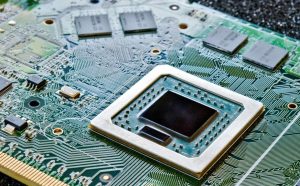
A flying-tail structure PCB is a rigid-flex circuit board in which a flexible circuit section extends from a rigid PCB region and functions as an integrated electrical interconnection.
Traditional electronic assemblies may use cables, wire harnesses, or board-to-board connectors to connect separate circuit boards. A flying-tail structure can integrate part of this interconnection directly into the PCB, potentially reducing the number of separate connection components.
The rigid portions provide mechanical support for components and mounting points, while the flexible tail allows the circuit to bend, fold, or pass through constrained mechanical spaces.
This combination makes the structure especially valuable for compact electronic products where conventional rigid boards and cable assemblies would consume too much internal volume.
Typical Applications
Flying-tail rigid-flex structures may be considered for:
- Smartphones and portable electronics
- Wearable devices
- Medical equipment
- Cameras and imaging equipment
- Communication equipment
- Industrial control systems
- Automotive electronics
- Aerospace and avionics equipment
- Compact sensors and IoT devices
For applications requiring flexible circuit fabrication and assembly, our Flex and Rigid-Flex PCB Assembly service provides additional manufacturing options.
How Is a Flying-Tail Structure PCB Manufactured?
The manufacturing process for a flying-tail PCB is more complex than that of a conventional rigid circuit board because rigid and flexible sections must work together mechanically and electrically.
A successful Rigid-Flex PCB Manufacturing process requires careful control of material selection, layer construction, lamination, drilling, copper plating, circuit imaging, coverlay or solder mask, surface finishing, and final inspection.
Circuit Pattern Formation
The manufacturing process begins with the preparation of the rigid and flexible materials required by the stack-up.
Copper foil is processed to create the required circuit patterns. Photolithography and controlled etching are commonly used to define traces, pads, and other conductive features.
In a flying-tail structure, the circuit pattern may extend from the rigid area into the flexible section. The transition between these regions must be designed carefully to avoid excessive mechanical stress.
Rigid and Flexible Layer Construction
The layer stack-up determines the electrical and mechanical characteristics of the finished board.
Rigid sections may use FR-4 or other rigid PCB materials, while flexible sections commonly use polyimide-based materials and copper conductors.
The stack-up must define:
- Number of rigid layers
- Number of flexible layers
- Copper thickness
- Dielectric materials
- Adhesive structures
- Overall board thickness
- Flexible tail dimensions
- Bend area and bend radius
For complex multilayer designs, early engineering review is important because stack-up decisions directly influence manufacturability, impedance, reliability, and cost.
Drilling and Via Formation
Mechanical drilling and laser drilling may be selected according to the PCB structure.
Through-holes, blind vias, and other interconnection structures must be manufactured within the specified dimensional tolerances. Hole quality, registration, aspect ratio, and copper plating are especially important in multilayer rigid-flex constructions.
Where the design permits, reducing unnecessary vias and connectors can simplify interconnection and improve the available routing space.
Copper Plating
After drilling, copper is deposited onto the required surfaces and inside plated holes.
Uniform copper coverage is essential because the PCB must maintain reliable electrical connections while also withstanding mechanical and thermal stresses during its operating life.
For complex PCB requirements, PCB Manufacturing capabilities can include multilayer, HDI, flexible, rigid-flex, high-frequency, heavy-copper, and controlled-impedance technologies.
Coverlay and Solder Mask
Flexible sections commonly require coverlay or an appropriate protective structure, while rigid sections may use conventional solder mask.
The selection and application of these protective materials should account for the required flexibility, bend radius, component mounting, soldering process, and environmental conditions.
Improper material selection around the flexible transition area can reduce bending performance and long-term reliability.
Surface Finish
A suitable surface finish is applied to exposed copper pads to protect them from oxidation and provide the required solderability or contact performance.
Common PCB surface finishes include:
- ENIG
- OSP
- HASL
- Immersion silver
- Immersion tin
- ENEPIG
- Gold plating for specialized contacts
The appropriate finish depends on the component package, assembly method, environmental requirements, and electrical interface.
Electrical Testing and Inspection
Finished flying-tail PCBs should undergo appropriate electrical and dimensional inspection before shipment.
Typical quality-control procedures can include:
- Electrical continuity testing
- Open and short testing
- AOI inspection
- Dimensional inspection
- Hole inspection
- Copper thickness verification
- Surface-finish inspection
- Solderability evaluation
- Impedance testing where required
For assembled boards, additional SMT, X-ray, functional, and other testing methods may be applied according to the project requirements.
Advantages of Flying-Tail Structure PCBs
A well-designed flying-tail PCB can provide several advantages over conventional rigid PCB and cable-based architectures.
Reduced Space and Weight
One of the main advantages of a flying-tail structure is the ability to integrate electrical interconnections into the PCB itself.
Replacing some cables, connectors, or separate flexible circuits can reduce the total number of components and make better use of internal product space.
This is particularly valuable for wearable electronics, portable devices, medical products, cameras, and aerospace equipment.
Improved Signal Integrity
Reducing unnecessary connectors and cable interfaces can help create a more continuous electrical path.
In high-speed applications, the interconnection architecture is an important part of overall signal integrity. Controlled impedance, return-path design, trace geometry, grounding, and stack-up selection should all be considered during PCB Design.
A rigid-flex structure can therefore be advantageous when compact mechanical integration and controlled electrical performance are required.
Fewer Interconnection Points
Every connector, cable, and mechanical interface introduces another potential point of electrical or mechanical failure.
By integrating rigid and flexible sections into one PCB structure, designers can reduce some external interconnection points.
This can help simplify assembly and potentially improve reliability in products exposed to vibration, mechanical movement, or repeated thermal cycling.
Better Mechanical Integration
The flexible tail can be routed through narrow spaces or around mechanical structures that would be difficult to accommodate using a conventional rigid PCB.
This enables three-dimensional electronic packaging and can allow designers to position rigid component-mounting areas exactly where they are needed.
Improved Product Integration
Rigid-flex structures can combine mechanical support and electrical connectivity within one component.
This can simplify the internal architecture of products and reduce the number of separate parts required for electrical interconnection.
For projects requiring both PCB fabrication and electronic assembly, PCB Assembly Services can provide an integrated manufacturing route from bare PCB to assembled electronics.
What Are the Limitations of Flying-Tail PCBs?
Although flying-tail structures provide significant design flexibility, they are not suitable for every PCB application.
Higher Manufacturing Complexity
Rigid-flex boards require specialized materials, stack-up design, lamination processes, and manufacturing controls.
As a result, their fabrication cost can be higher than that of conventional rigid PCBs.
The additional engineering and processing requirements should therefore be considered during the early stages of product development.
More Complicated Mechanical Design
The flexible tail must have sufficient space to bend or route through the product without exceeding its mechanical limitations.
The bend radius, bend direction, copper thickness, number of layers, and flexible material all affect mechanical reliability.
Component Placement Restrictions
Components should generally be kept away from areas that require repeated bending unless the structure has been specifically engineered for that purpose.
The transition between rigid and flexible sections also requires sufficient clearance to avoid mechanical stress concentrations.
Limited Design Compatibility
A flying-tail structure may not be appropriate when the product architecture requires extremely high component density throughout the entire PCB.
In such cases, a conventional multilayer, HDI, or other PCB architecture may provide a better balance between routing density, manufacturability, and cost.
What Should Be Avoided When Designing a Flying-Tail PCB?
Successful PCB Design requires the electrical, mechanical, and manufacturing requirements to be considered together.
Avoid Ignoring the Complete Mechanical Structure
Do not design the flexible tail independently from the final product enclosure.
The PCB should be evaluated in its actual three-dimensional installation environment.
Check:
- Bending direction
- Bend radius
- Mechanical clearance
- Connector position
- Component height
- Mounting points
- Housing interference
- Cable and connector clearance
A 3D mechanical model can help identify potential interference before prototype production.
Avoid Incorrect Layer Stack-Up
The layer stack-up should be defined before routing begins.
For rigid-flex boards, designers should consider the relationship between rigid layers, flexible layers, copper thickness, dielectric thickness, impedance requirements, and mechanical bending requirements.
A poorly balanced stack-up can create unnecessary manufacturing difficulty or mechanical stress.
Avoid Excessive Copper in Bend Areas
Copper does not behave like a flexible dielectric material. Thick copper, wide copper areas, and inappropriate trace routing can reduce flexibility and increase mechanical stress.
Where repeated bending is required, the conductor layout should be optimized specifically for flexing conditions.
Avoid Placing Components Too Close to the Flex Transition
Components, vias, and large copper structures located too close to the rigid-to-flex transition can increase mechanical stress.
Adequate keep-out areas should be incorporated according to the manufacturer’s process recommendations.
Avoid Treating a Rigid-Flex PCB Like a Standard Rigid PCB
A flexible region should not simply be considered a thinner version of a rigid board.
Material selection, bend radius, copper geometry, coverlay, adhesive systems, and mechanical loading all influence the final reliability of the product.
Early DFM review can help identify problems before tooling and production begin.
Flying-Tail PCB Assembly Considerations
Assembly is another important consideration when using a flying-tail structure.
The flexible section may require special handling and fixtures to prevent excessive bending during solder paste printing, component placement, reflow, inspection, and testing.
Depending on the design, the board may use:
- SMT assembly
- Through-hole assembly
- Mixed-technology assembly
- BGA assembly
- Fine-pitch component assembly
- Functional testing
- X-ray inspection
- AOI inspection
For prototype and production projects, Rapid PCB Prototyping can help validate the PCB structure and assembly process before larger-scale production.
How to Choose a Flying-Tail PCB Manufacturer
Choosing an experienced manufacturer is particularly important for advanced rigid-flex structures.
A capable supplier should understand both conventional PCB fabrication and flexible-circuit manufacturing.
Important evaluation criteria include:
- Rigid-flex manufacturing experience
- Flexible material availability
- Multilayer PCB capability
- Laser and mechanical drilling
- Controlled lamination
- Copper plating capability
- Electrical testing
- AOI and inspection systems
- DFM engineering support
- PCB assembly capability
- Prototype and production support
A manufacturer with integrated PCB fabrication and assembly capabilities can also simplify communication between engineering, fabrication, and assembly teams.
GOPCBA provides PCB manufacturing and PCBA services covering rigid, flexible, rigid-flex, HDI, high-frequency, high-TG, heavy-copper, and other specialized PCB technologies.
Quality Control for Flying-Tail Structure PCBs

Quality control should cover the entire manufacturing process rather than relying only on final inspection.
A comprehensive quality program may include:
- Engineering review
- DFM analysis
- Material verification
- Stack-up verification
- Inner-layer inspection
- Lamination inspection
- Hole and via inspection
- Copper thickness measurement
- AOI
- Electrical testing
- Dimensional inspection
- Surface-finish inspection
- Assembly inspection
- Functional testing
For assembled rigid-flex products, manufacturing capabilities can include rigid, flexible, and rigid-flex PCB assembly with SMT and through-hole technologies.
Flying-Tail Structure PCB Applications
Flying-tail structures are most valuable when electrical connectivity must coexist with mechanical flexibility and restricted installation space.
Consumer Electronics
Smartphones, wearable devices, cameras, portable electronics, and other compact products can benefit from reduced wiring and three-dimensional PCB integration.
Medical Electronics
Medical equipment often requires compact electronics, reliable interconnections, and carefully controlled mechanical packaging.
Rigid-flex structures can help integrate electronic modules into constrained medical-device housings.
Aerospace and Avionics
Aerospace electronics often prioritize weight reduction, reliability, vibration resistance, and efficient use of available space.
A properly engineered rigid-flex structure can help reduce separate wiring and connectors.
Automotive Electronics
Automotive electronics may experience vibration, temperature cycling, and severe space constraints.
Flying-tail structures can be considered for compact control modules, sensors, displays, cameras, and other electronic systems.
Industrial Equipment
Robotics, automation systems, motion-control equipment, sensors, and industrial instruments can use flexible interconnections where PCB sections need to move or occupy irregular mechanical spaces.
Flying-Tail PCB vs. Conventional Rigid PCB
The main difference is mechanical architecture.
A conventional rigid PCB is primarily designed to remain flat and structurally stable. A flying-tail PCB combines rigid mounting areas with flexible interconnection sections.
This makes rigid-flex technology particularly useful for three-dimensional products, moving assemblies, and compact electronic systems.
The appropriate technology should ultimately be selected according to electrical requirements, mechanical constraints, production volume, reliability requirements, and total system cost.
Frequently Asked Questions
What is a Flying-Tail Structure PCB?
A Flying-Tail Structure PCB is a specialized rigid-flex circuit board in which a flexible PCB section extends from a rigid PCB area to provide integrated electrical interconnection and mechanical flexibility.
Is a Flying-Tail PCB the same as a Rigid-Flex PCB?
A flying-tail PCB can be considered a specialized structural implementation of rigid-flex technology. The defining characteristic is the flexible tail extending from or between rigid PCB sections.
What materials are commonly used?
Rigid sections commonly use FR-4 or other rigid PCB materials, while flexible sections typically use polyimide-based substrates, copper conductors, coverlay, and suitable bonding materials.
Are Flying-Tail PCBs expensive?
They can cost more than conventional rigid PCBs because they require specialized materials, multilayer construction, lamination, flexible-section processing, and additional engineering controls.
However, the overall system cost can sometimes be reduced by eliminating cables, connectors, and separate flexible circuits.
Can Flying-Tail PCBs be assembled with SMT?
Yes. Rigid-flex PCBs can support SMT, through-hole, or mixed-technology assembly depending on the board structure and component requirements. Proper fixtures and handling procedures are important when flexible sections are present.
What information is needed for a quotation?
A manufacturer will typically need Gerber files, PCB stack-up information, board drawings, material requirements, copper thickness, surface finish, BOM and assembly files where applicable, quantities, and any special mechanical or electrical requirements.
Conclusion
A Flying-Tail Structure PCB provides a specialized solution for electronic products that require rigid component-mounting areas combined with flexible integrated interconnections.
By reducing cables and connectors, improving three-dimensional packaging, saving internal space, and supporting controlled electrical interconnections, this technology can provide important advantages for compact and high-reliability electronic products.
However, successful implementation depends on careful stack-up design, material selection, bend-radius control, rigid-to-flex transition design, manufacturing engineering, and assembly handling.
For demanding applications, working with an experienced Rigid-Flex PCB Manufacturing partner from the design stage can help reduce manufacturing risks, improve reliability, and create a more efficient path from prototype to production.
GOPCBA supports rigid, flexible, rigid-flex, multilayer, HDI, high-frequency, and other advanced PCB technologies, together with PCB assembly and engineering support for prototype and production applications.
Start your next Flying-Tail PCB project with GOPCBA and provide your Gerber files, stack-up, drawings, BOM, and technical requirements for engineering evaluation.