Why PCB Drill Files and Drill Drawings Matter
When preparing manufacturing files for PCB fabrication, designers often focus on copper layers, solder mask, silkscreen, and board outlines while overlooking drilling documentation. However, a complete manufacturing package should clearly define both the PCB drill files and PCB drill drawing whenever the design requires plated holes, non-plated holes, slots, or other mechanical features.
A PCB drill file contains machine-readable information that defines hole locations, hole sizes, and drilling operations. A drill drawing, also called a drill map or drill chart, provides a visual reference that allows engineers to understand and verify the drilling data.
For reliable PCB manufacturing data, these two types of information should be checked together before the files are released for production.
For projects requiring complete fabrication support, see our PCB Manufacturing capabilities and manufacturing specifications.
1. PCB Manufacturing Data Without a Drill File
One common problem occurs when a designer provides Gerber layers and a drill drawing but does not include an actual NC drill file.
Although a drill drawing can visually represent the holes, it is not normally a direct machine-control file. Different symbols are typically assigned to different drill diameters, and the manufacturing engineer would have to interpret the drawing and recreate the drilling information.
This manual conversion increases engineering workload and creates opportunities for errors.
Potential problems include:
- Incorrect hole diameter
- Missing holes
- Incorrect hole coordinates
- Incorrect hole quantities
- Confusion between plated and non-plated holes
- Missing slots or mechanical features
Therefore, the recommended approach is to provide the corresponding NC drill files together with the Gerber data.
2. What Is a PCB Drill Drawing?
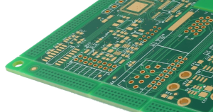
A PCB drill drawing is a visual representation of the holes defined in the PCB design.
It normally includes:
- Hole locations
- Drill symbols
- Drill sizes
- Hole quantities
- Hole legends or charts
- Plated and non-plated hole information
- Mechanical or slot features when applicable
The drill drawing is particularly useful during CAM engineering because it provides an additional reference for checking the machine-readable drilling data.
A complete production package should also include the board outline, copper layers, solder mask, silkscreen, and other required manufacturing information. Our Rapid PCB Prototyping documentation also identifies drill data as an important part of the PCB production file set.
3. Why Use PCB Drill Files and Drill Drawings Together?
The biggest advantage of using both files is cross-checking.
The NC drill files provide manufacturing coordinates and drill instructions, while the drill drawing provides a visual reference for engineering verification.
During CAM preparation, engineers can compare the two to identify:
Hole Quantity Errors
The engineer can compare the number of holes shown in the drill drawing with the number of holes contained in the drill data.
This can help detect missing or duplicated holes before fabrication.
Hole Position Errors
The drill drawing can be used as a visual reference to identify abnormal hole locations or possible registration problems.
Plated and Non-Plated Hole Identification
Different hole types may require different manufacturing processes.
For example:
- Plated through holes require copper plating on the hole wall.
- Non-plated through holes do not require plated hole walls.
- Mechanical holes may be produced using drilling or routing.
- Slots may require milling depending on their geometry and manufacturing requirements.
Clearly identifying these features helps reduce interpretation errors during production.
4. Slot Holes Require Special Attention
One of the most important reasons to provide a drill drawing is to prevent missing mechanical slots.
Not every elongated or irregular hole can be represented in the same way as a conventional round drilled hole.
For example, an L-shaped slot, elongated slot, or irregular mechanical opening may need to be defined in a mechanical or milling layer rather than treated as a conventional circular drill.
If the designer provides neither appropriate milling information nor a clear drill drawing, the manufacturing engineer may not recognize the feature correctly.
This can result in a finished PCB with missing slots or incorrect mechanical openings.
For more complex designs, professional PCB Design and Layout support can help verify manufacturing documentation before production.
5. PCB Drill Files vs. Drill Drawings
Although they are closely related, PCB drill files and drill drawings serve different purposes.
| Item | PCB Drill File | PCB Drill Drawing |
|---|---|---|
| Main purpose | Machine-readable drilling data | Engineering verification |
| Format | NC drill / Excellon or equivalent | Gerber or drawing/document |
| Hole coordinates | Yes | Visual representation |
| Drill diameter | Yes | Yes |
| Hole quantity | Defined by data | Clearly shown for checking |
| Direct machine use | Yes, depending on format and process | No |
| Engineering cross-check | Limited visually | Very useful |
| Plated/non-plated identification | Depends on design/file structure | Can provide visual reference |
The important point is that these files are complementary rather than interchangeable.
6. What About Non-Plated Holes?
Non-plated through holes can create confusion because they may be represented differently depending on the PCB design software and manufacturing workflow.
For simple circular non-plated holes, drill data can generally define the required hole size and position.
However, special mechanical features such as irregular slots may need to be represented through appropriate milling or mechanical data.
Therefore, designers should not rely on the drill drawing alone. The complete manufacturing package should clearly distinguish:
- Plated through holes
- Non-plated through holes
- Via holes
- Mechanical holes
- Slots
- Cutouts
This becomes increasingly important as board complexity increases.
7. What Files Should Be Included in a PCB Production Package?
A typical PCB production package may include:
- Top copper layer
- Bottom copper layer
- Inner copper layers for multilayer PCBs
- Top solder mask
- Bottom solder mask
- Top silkscreen
- Bottom silkscreen
- Board outline
- NC drill files
- PCB drill drawing
- Mechanical or milling files when required
- Stack-up information
- PCB fabrication drawing
- Special manufacturing requirements
For PCBA projects, additional files such as BOM and pick-and-place data are required. Our One-Stop PCBA Manufacturing Services provide an overview of the complete production data package.
8. How to Prepare PCB Drill Data Correctly
Before exporting your manufacturing files, follow these steps.
Step 1: Verify All Hole Types
Review the PCB design and identify every type of hole:
- Through-hole vias
- Through-hole component holes
- Blind vias
- Buried vias
- Non-plated holes
- Mechanical holes
- Slots
Make sure every feature has been assigned the correct manufacturing definition.
Step 2: Generate the NC Drill File
Export the NC drill data from your PCB design software.
Common PCB design tools can generate drill files in formats supported by PCB manufacturers.
Make sure the drill origin and coordinate system are consistent with the rest of the manufacturing data.
Step 3: Generate the Drill Drawing
Create a drill drawing showing the drill symbols, hole sizes, quantities, and other relevant information.
The drill chart should be positioned clearly outside the PCB artwork whenever possible.
Step 4: Check the Drill Chart
Verify that the drill table does not overlap the PCB itself.
Overlapping tables, labels, or symbols can make the manufacturing documentation difficult to interpret.
Step 5: Compare the Files
Finally, compare the drill drawing against the NC drill file and PCB layout.
Check:
- Number of holes
- Hole sizes
- Hole locations
- Hole types
- Slots
- Mechanical openings
- Plated/non-plated definitions
A professional DFM review can further reduce manufacturing risks. Our PCB Assembly Services include engineering support such as Gerber review, DFM analysis, BOM verification, and manufacturing documentation verification.
9. Common Problems When Drill Data Is Incomplete

Incomplete drilling documentation can lead to several manufacturing problems.
Missing Drill File
The manufacturer may not have machine-readable drilling coordinates, resulting in additional engineering work or a request for revised files.
Missing Drill Drawing
Without a visual reference, it becomes more difficult to cross-check hole quantities, hole types, and possible design errors.
Missing Slot Data
This is particularly risky for elongated or irregular slots because they may not be interpreted correctly as standard drilled holes.
Incorrect Hole Classification
If plated and non-plated holes are not clearly distinguished, the resulting PCB may not meet the electrical or mechanical requirements of the design.
Incorrect Drill Sizes
Even a small error in drill diameter can affect component insertion, via reliability, mechanical assembly, or electrical performance.
10. Best Practices for PCB Designers
To create reliable Gerber files, follow these practical recommendations:
Always Export the NC Drill File
Do not assume that the drill drawing can replace the machine-readable drill file.
Always Include a Drill Drawing When Possible
The drawing provides an additional reference for CAM engineering and quality control.
Keep the Drill Chart Clear
Place the chart away from the PCB artwork so that symbols and tables do not overlap the board.
Clearly Define Special Holes
Slots, cutouts, mechanical holes, and unusual geometries should be clearly identified in the manufacturing data.
Check the Complete Production Package
Before sending files to a manufacturer, inspect the entire package rather than checking individual Gerber layers independently.
Use Manufacturer Design Rules
Different PCB manufacturers have different minimum drill sizes, aspect ratios, layer counts, and fabrication capabilities. Always check the manufacturer’s current capabilities before finalizing the design.
For example, our PCB Capabilities page provides information about minimum mechanical and laser drill sizes, PCB thickness, layer count, aspect ratio, copper weight, and other fabrication capabilities.
11. Final PCB Manufacturing Checklist
Before submitting your PCB files for production, verify the following:
- Gerber files are complete
- NC drill files are included
- PCB drill drawing is included
- Drill sizes are correct
- Hole quantities are correct
- Plated and non-plated holes are correctly identified
- Slot and milling information is included
- Board outline is correct
- Drill origin is consistent
- Drill chart does not overlap the PCB
- Special manufacturing requirements are documented
- Final files have been checked against the PCB design
Conclusion
A reliable PCB production package is more than a collection of Gerber layers. PCB drill files provide the machine-readable information required for drilling, while the PCB drill drawing provides an important visual reference for engineering verification.
Using both together makes it easier to identify missing holes, incorrect drill sizes, incorrect hole classifications, and missing slots before fabrication. This is especially important for complex multilayer boards, high-density designs, and PCBs containing multiple mechanical features.
For production projects, the safest approach is to prepare a complete manufacturing package containing Gerber files, NC drill data, drill drawings, board outlines, mechanical information, and all required fabrication notes.
If you are preparing a PCB or PCBA project and want engineering support before production, you can submit your manufacturing files through our PCB Manufacturing and Assembly Services for review and quotation.